2.
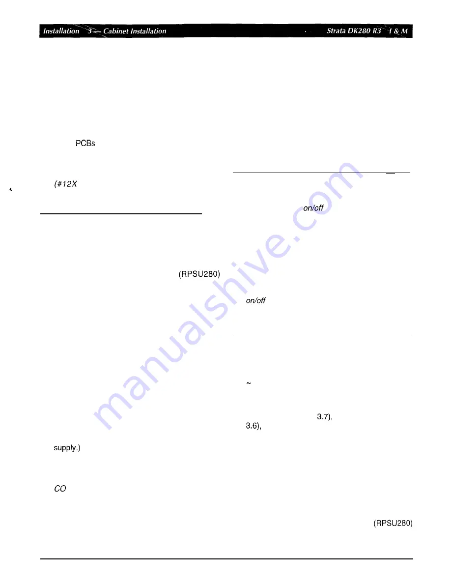
Mount cabinets on floor or wall (see Section 3.4 or
3.5).
3.
Install ground wiring (see Section 3.6).
4.
Install AC power cabling
to
cabinets (see Section
3.7).
5.
Install reserve power cabling (see Section
3.8).
6.
Install
and PCB cabling (see Figures 3-10,
3-12,
and 3-1 3).
Note:
Each cabinet requires four wood screws
7.25
inch size) for wall mount
installation. Wood screws are not provided
with the system.
3.3
Power
supply
Installation and
Removal
3.3.1
Installation
The base and expansion cabinets are shipped from
the factory without the power supply
installed. Refer to the following instructions and
Figures 3-1 and 3-2 to install power supplies in
cabinets of new or installed systems:
1.
Remove the power supply from its box. The box
should also contain a plastic bag with two jumper
plugs for the power supply DKSUB or DKSUE
connector. An AC power cord and the power
supply mounting screws are provided with the
KSU
cabinet.
2.
Make sure that the front and right side covers are
removed from the cabinet (Figure 3-1).
3.
Slide the power supply into the right side of the
cabinet
so
that its four mounting holes align with
the four cabinet mounting holes. (Make sure that
the two backplane FG wires are positioned
between the
FG
wire holder and the power
Note:
The backplane
FG
wires are not safety
grounds, they are required for proper system
line operation.
4.
Plug the DC
OUT
cable plug into the DC
OUT
connector on the power supply. (The plug has a
guide key on
it
to
ensure that it is plugged in
correctly.)
5.
Secure the FG wire spade lug to the power supply
with the FG screw.
6.
Secure the power supply
to
the cabinet with the
four provided screws.
7. If the cabinet is the base unit, plug the jumper plug
that has a wire connected into the “DKSUB”
jumper connector on the power supply.
8.
If the cabinet is an expansion unit (DKSUE), plug
the jumper plug that does not have a wire
connected into the “DKSUE” jumper connector.
IMPORTANT!
The power supply with the “DKSUB” jumper
plug (plug with wire) installed is called the
master and has
control over all other
power supplies, which are designated as
slaves. If the master power supply is turned
off or on, all other power supplies will
automatically turn
off or on. (Individual power
supplies must be turned on.)
Power supplies that have the “DKSUE”
jumper plugs (plug without wire) installed will
not control other power supplies, but can be
turned off or on individually with their own
switch. (The master power supply must
be on and the intercabinet “Data” ribbon cable
must be installed to allow a slave power
supply to be turned on.)
9.
Refer to Figure 3-3 to ensure that the power
supply is properly installed.
10.
Install power supplies in all cabinets, using steps 1
9.
11.
Install the base and optional expansion cabinets
per Section 3.4 or 3.5, install applicable AC
cabling (per Section
ground wiring (Section
and reserve power cabling (Section 3.8) to
the power supply.
Note:
Power Supply testing procedures are
provided in the Fault Finding section, which
should be referred to if it is suspected that the
power supply does not work properly.
3.3.2
Removal
Use
the following instructions and refer to Figures 3-1,
3-2,
and 3-3 to remove power supplies
from cabinets of installed systems.
3-2
January
1996
Summary of Contents for Strata AirLink DK280
Page 12: ...I ...
Page 68: ...January1996 1 56 ...
Page 85: ...MARKING HOLE BACK COVER DK0181 Figure 3 8 Back Cover Mounting Holes 3 11 January1996 ...
Page 86: ...DKOl82 Figure 3 9 Mounting Cabinet on Back Cover 3 12 January1996 ...
Page 114: ...I ...
Page 180: ...4 64 January 1996 ...
Page 274: ...January 1996 ...
Page 326: ... February 1996 ...
Page 340: ......
Page 358: ... 8 l 8 January 1996 ...
Page 360: ......
Page 414: ... 9 54 January 1996 ...
Page 416: ......
Page 455: ......
Page 465: ...Program 29 Initialized DSS Console Button Assignments DK0126 January 1996 1 o 49 ...
Page 499: ......
Page 532: ......
Page 573: ... il Restriction System Record Sheets Programs 40 48 lanuary 1996 1 o 1 59 ...
Page 591: ......
Page 599: ...Least Co Routing System Record Sheets y 7 I _ _ r __ Programs 50 56 January 1996 ...
Page 617: ......
Page 619: ......
Page 644: ...11 20 January 1996 ...
Page 703: ...13 40 January 1996 ...
Page 704: ......
Page 706: ......
Page 766: ......
Page 782: ...U l 58 January 1996 ...
Page 783: ......
Page 784: ......
Page 785: ......
Page 786: ......
Page 787: ......
Page 788: ......
Page 789: ......
Page 790: ......
Page 791: ......
Page 792: ......
Page 793: ......
Page 794: ......
Page 795: ......
Page 796: ......
Page 797: ......
Page 798: ......
Page 799: ......
Page 800: ......
Page 801: ......
Page 802: ......
Page 803: ......
Page 804: ......
Page 805: ......
Page 806: ......
Page 807: ......
Page 808: ......
Page 809: ......
Page 810: ......
Page 811: ......
Page 812: ......
Page 813: ......
Page 814: ......
Page 815: ......
Page 816: ......
Page 817: ......
Page 818: ......
Page 819: ......
Page 820: ......
Page 821: ......
Page 822: ......
Page 823: ......
Page 824: ......
Page 825: ......
Page 826: ......
Page 827: ......
Page 828: ......
Page 829: ......
Page 830: ......
Page 831: ......
Page 832: ......
Page 833: ......
Page 834: ......
Page 835: ......
Page 836: ......
Page 837: ......
Page 838: ......
Page 839: ......
Page 840: ......
Page 841: ......
Page 842: ......
Page 843: ......
Page 844: ......
Page 845: ......
Page 846: ......
Page 847: ......
Page 848: ......
Page 849: ......
Page 850: ......
Page 851: ......
Page 852: ......
Page 853: ......
Page 854: ......
Page 855: ......
Page 856: ......
Page 857: ......
Page 858: ......
Page 877: ...I ...
Page 878: ...I ...


