


13
Introduction
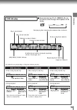
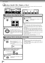
DVD display
The indicators vary depending on the kinds of discs you play.
DVD video disc
Audio CD
Example
Some discs may not display chapter
numbers or elapsed time.
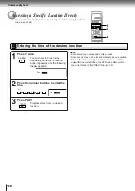
Repeated pressing of the FL DIMMER button on
the remote control changes the brightness of the
display.
Repeat playback indicator
Angle icon indicator
Total playing time/remaining time/elapsed time indicators
Memory playback indicator
Chapter number indicator
Title/track number indicator
Play mode indicator
DVD/VIDEO CD/CD indicator
Multifunctional indicator (indicates operating
status or messages, etc.)
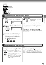
Total number of titles
• When closing the disc tray:
• During playback:
Playing chapter 3
of title 2
Elapsed time
of the current
title
Example
• When closing the disc tray:
Example
Total number of
tracks
Total playing
time of the disc
• During playback:
Example
Playing track 6
Elapsed time of
the current
track
Normal
Off
Dimmed
Disc number indicator
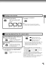
VIDEO CD
• When closing the disc tray:
Example
Total number of
tracks
Total playing
time of the disc
• During playback:
Example
Playing track 6
Elapsed time of
the current
track
Some discs may not display track
numbers or elapsed time.
DISC TITLE TRK
CHP
INDEX
TOTAL
REMAIN
MEMORY
HDCD
S
V C D V D
DISC TITLE
TRK
CHP
INDEX
TOTAL
REMAIN
MEMORY
HDCD
S V C
D V D
DISC
TITLE
TRK
CHP INDEX
TOTAL
REMAIN
MEMORY
HDCD
S
V C D
V D
DISC
TITLE
TRK
CHP INDEX
TOTAL
REMAIN
MEMORY
HDCD
S V
C D
V D
DISC TITLE
TRK
CHP INDEX
TOTAL
REMAIN
MEMORY
HDCD
S V C
D V D
DISC
TITLE
TRK
CHP INDEX
TOTAL
REMAIN
MEMORY
HDCD
S
V C D
V D
DISC
TITLE
TRK
CHP INDEX
TOTAL
REMAIN
MEMORY
HDCD
S V
C D
V D
FL DIMMER
Summary of Contents for SD-2050
Page 1: ...DVD VIDEO PLAYER SERVICE MANUAL May 2000 s FILE NO 810 200005 SD 2050 DIGITAL VIDEO ...
Page 5: ...SECTION 1 GENERAL DESCRIPTIONS SECTION 1 GENERAL DESCRIPTIONS 1 OPERATING INSTRUCTIONS ...
Page 51: ...47 Others Memo ...
Page 80: ...4 2 Power Supply Block Diagram Fig 3 4 2 ...
Page 82: ...Fig 3 4 5 4 3 3 Front Display Power Switch Block Diagram ...
Page 84: ...Fig 3 4 7 4 4 2 Logical System Block Diagram ...
Page 85: ...4 5 Output Block Diagram Fig 3 4 8 ...
Page 88: ...10 1 3 4 A B C D E G 2 5 6 7 8 9 F Fig 3 5 3 5 2 Front Display Power Switch Circuit Diagram ...
Page 95: ...Fig 3 5 5 5 3 2 Main Circuit Diagram ...
Page 96: ...5 3 2 Main Circuit Diagram ...
Page 97: ......
Page 98: ......
Page 99: ......
Page 100: ......
Page 101: ......
Page 102: ......
Page 103: ...Fig 3 5 5 ...
Page 105: ...Fig 3 5 6 10 1 3 4 A B C D E G 2 5 6 7 8 9 F 11 H 5 4 Output Circuit Diagram ...
Page 115: ...10 1 3 4 A B C D E G 2 5 6 7 8 9 F Fig 3 6 6 EU01 Main PC Board Top pattern character symbol ...
Page 125: ......


