3 Diagnostic Programs
3.2 Quick Start
18
Satellite A100/A105 / TECRA A7 Maintenance Manual
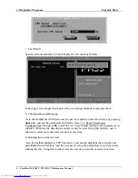
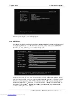
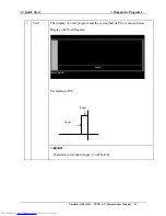
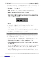
On the left column of the above screen, the detected hardware components are listed. The
corresponding information of the detected hardware components is displayed on the right
of the screen. It displays the current running status information of the check program.
The name of the program is marked on the top of the screen. At the bottom, the function
keys are listed for user operation. During the detection, keyboard operation is invalid.
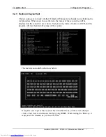
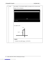
When the detection is finished, the hardware components information will be displayed
as follows:
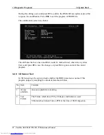
User can use function keys listed on the bottom of the screen to display the configuration
of the component or exit the current program. On the left column, the components
information is listed and user can use arrow keys or
PgUp/PgDn
to view the list and
highlight the chosen component. On the right column, the configuration information of
the highlighted component is listed. Press
ESC
to exit this program.
Summary of Contents for Satellite A100 Series
Page 2: ...ii S No ...
Page 15: ...Chapter 1 Hardware Overview ...
Page 16: ...1 Hardware Overview ii Satellite A100 A105 TECRA A7 Maintenance Manual ...
Page 53: ...2 Troubleshooting 2 4 System Board 2 10 Satellite A100 A105 TECRA A7 Maintenance Manual ...
Page 73: ...Chapter 3 Diagnostic Programs ...
Page 76: ......
Page 115: ...3 5 System Test 3 Diagnostic Programs Satellite A100 A105 TECRA A7 Maintenance Manual 39 ...
Page 146: ...Chapter 4 Replacement Procedures 4 1 ...
Page 147: ...4 Replacement Procedures 4 ii Satellite A100 A105 TECRA A7 Maintenance Manual ...
Page 154: ...4 Replacement Procedures 4 1 General 4 2 Satellite A100 A105 TECRA A7 Maintenance Manual ...
Page 222: ...6000 1 Appendices ...
Page 223: ...Appendices App ii Satellite A100 A105 TECRA A7 Maintenance Manual ...

