background image

– 74 –

Concealed Duct High Static Pressure

Owner’s Manual

Concealed Duct High Static Pressure

Owner’s Manual

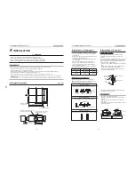
Air discharge

Connect a discharge duct.

Remote controller

Separate sold part

Air intake

Connect a suction duct.

Drain pan

Electrical control box

The earth screw is provided in the 
electrical control box.

Air intake 

(Side and rear)

Front panel

There is an earth screw, valves, 
and electric parts inside.

Air discharge

Pipe cover

Wire connection holes

Refrigerant pipe connection 

holes

Mounting leg

2

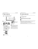
PART NAMES

n

Indoor unit

n

Outdoor unit

SET

TIME

TIMER SET

TEST

FILTER

RESET

TEMP.

CL

FAN

SAVE

SWING/FIX

VENT

MODE

ON / OFF

UNIT  LOUVER

Display 
section

Operation 
section

1

8

6

4

2

3

5
7

13

15

14

9

12

11

10

3

WIRED REMOTE CONTROLLER

This remote controller can control the operation of up to 8 indoor units.

n

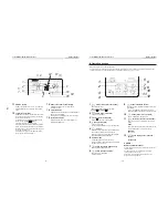
Display section

In the display illustration below all the icons are shown.
When the unit is in operation, only relevant icons will be displayed.
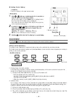
• When turning on the leak breaker at the first time, 

 flashes

on the display part of the remote controller.

• While this icon is flashing, the model is being automatically confirmed.

Wait till 

 icon has disappeared to use the remote controller.

1

Operation mode

The selected operation mode is displayed.

2

Error display

Displayed while the protective device works or a

error occurs.

3

SETTING display

Displayed during setup of the timer or other settings.

4

TEST run display

Displayed during a test run.

5

Timer display

When an error occurs, error code is displayed.

6

Timer mode display

The selected timer mode is displayed.

7

Filter display

Reminder to clean the air filter.

8

Fan speed display

Fan speed is not adjustable.  It is fixed to High.

(HIGH) 

9

Set temperature display

The selected set temperature is displayed.

10

Power saving mode display

Limits compressor speed (capacity) to save

energy.

– 7 –

– 8 –

Summary of Contents for RAV-SM2242DT-E

Page 1: ...R410A PRINTED IN JAPAN Apr 2010 ToMo FILE NO A10 001 Revised May 2010 SERVICE MANUAL SPLIT TYPE INDOOR UNIT DIGITAL INVERTER RAV SM2242DT E RAV SM2802DT E RAV SM2242DT TR RAV SM2802DT TR ...

Page 2: ...door Controller Block Diagram 22 6 2 Control Specifications 23 6 3 Indoor Print Circuit Board 30 7 INDOOR UNIT TROUBLESHOOTING 32 7 1 Summary ofTroubleshooting 32 8 REPLACEMENT OF SERVICE P C BOARD 51 8 1 Indoort Unit 51 9 SETUP AT LOCAL SITE AND OTHERS 55 9 1 Indoor Unit 55 9 2 Setup at Local Site Others 62 9 3 How to Set up Central Control Address Number 64 10 ADDRESS SETUP 66 10 1 Address Setup...

Page 3: ... has been instructed in such matters by an individual or individuals who have been trained and is thus thoroughly acquainted with the knowledge related to this work The qualified installer who is allowed to work at heights has been trained in matters relating to working at heights with the air conditioners made by Toshiba Carrier Corporation or alternatively he or she has been instructed in such m...

Page 4: ...tems thoroughly in the following contents Indications Illustrated marks and keep them Explanation of indications Indication DANGER WARNING CAUTION Explanation Indicates contents assumed that an imminent danger causing a death or serious injury of the repair engineers and the third parties when an incorrect work has been executed Indicates possibilities assumed that a danger causing a death or seri...

Page 5: ...get burned when removing this panel CAUTION Do not touch the aluminum fins of the unit Doing so may result in injury CAUTION BURST HAZARD Open the service valves before the operation otherwise there might be the burst Description WARNING ELECTRICAL SHOCK HAZARD Disconnect all remote electric power supplies before servicing WARNING Moving parts Do not operate unit with grille removed Stop the unit ...

Page 6: ...stry as protective gear to undertake the work When working at heights put a sign in place so that no one will approach the work location before proceeding with the work Parts and other objects may fall from above possibly injuring a person below Do not touch the aluminum fin of the outdoor unit You may injure yourself if you do so If the fin must be touched for some reason first put on protective ...

Page 7: ...epair or relocation work check that the ground wires are connected properly Be sure to connect earth wire Grounding work Incomplete grounding causes an electric shock Do not connect ground wires to gas pipes water pipes and lightning rods or ground wires for telephone wires Do not modify the products Do not also disassemble or modify the parts It may cause a fire electric shock or injury When any ...

Page 8: ... refrigerant with recovering device The refrigerant cannot be recovered in the outdoor unit otherwise a serious accident such as breakage or injury is caused After repair work surely assemble the disassembled parts and connect and lead the removed wires as before Perform the work so that the cabinet or panel does not catch the inner wires If incorrect assembly or incorrect wire connection was done...

Page 9: ... unit is to be opened in order for the compressor or the area around this part to be repaired immediately after the air conditioner has been shut down set the circuit breaker to the OFF position and then wait at least 10 minutes before opening the service panel If you fail to heed this warning you will run the risk of burning yourself because the compressor pipes and other parts will be very hot t...

Page 10: ...ssibly resulting in reputing injury etc 1 Refer to the Definition of Qualified Installer or Qualified Service Person Declaration of Conformity Manufacturer Toshiba Carrier Corporation 336 Tadehara Fuji shi Shizuoka ken 416 8521 JAPAN Authorized Nick Ball Representative TCF holder Toshiba EMEA Engineering Director Toshiba Carrier UK Ltd Porsham Close Belliver Industrial Estate PLYMOUTH Devon PL6 7D...

Page 11: ... others do not mix in because pipes are affected by impurities such as water oxide scales oil etc Use the clean pipes Be sure to brazing with flowing nitrogen gas Never use gas other than nitrogen gas 4 For the earth protection use a vacuum pump for air purge 5 R410A refrigerant is azeotropic mixture type refrigerant Therefore use liquid type to charge the refrigerant If using gas for charging com...

Page 12: ...ng of flare nut Evacuating refrigerant charge run check etc Vacuum evacuating Refrigerant charge Refrigerant charge Gas leakage check R410A air conditioner installation Existence of Whether conventional new equipment for R410A equipment can be used Yes Note Yes Note Yes No Yes No Yes No Yes Yes Yes No Yes No Conventional air conditioner installation Whether conventional equipment can be used Yes N...

Page 13: ...unit kg Heat exchanger Fan Standard air flow at 137Pa at Mid tap m min Fan unit Fan Speed Motor W External static pressure H M L Pa Air filter Controller Sold Separately Sound pressure level H M L dB A Sound power level H M L dB A Gas side mm Connecting pipe Liquid side mm Drain port mm RAV SM2242DT E RAV SM2802DT E RAV SM2242AT8 E RAV SM2802AT8 E 20 0 23 0 22 4 27 0 1 phase 220 240V 50Hz 5 25 4 8...

Page 14: ...exchanger Fan Standard air flow at 137Pa at Mid tap m min Fan unit Fan Speed Motor W External static pressure H M L Pa Air filter Controller Sold Separately Sound pressure level H M L dB A Sound power level H M L dB A Gas side mm Connecting pipe Liquid side mm Drain port mm RAV SM2242DT TR RAV SM2802DT TR RAV SM2244AT8 E RAV SM2804AT8 E 20 0 23 0 22 4 27 0 1 phase 220 240V 50Hz 5 25 4 81 5 25 4 81...

Page 15: ...conditioner Check and cleaning port Attention Be sure to set the plug and to make it to be able to cleaning because garbage in drain piping piles up easily in drain trap Plug Check panel 50 100 1000 or more 200 Space required for installation and serving Service space Check port Service space or more Hole for hanging bolt Hanging bolt mounting pitch Hanging bolt mounting pitch Electric parts box S...

Page 16: ... TR Dimension table Indoor unit TCJ sensor Air heat exchanger TC sensor Distributor Strainer incorporated Refrigerant pipe at liquid side ØB Refrigerant pipe at gas side ØA To outdoor unit To outdoor unit Heating Cooling Indoor unit SM224 SM280 type Outer diameter of refrigerant pipe Gas side ØA Liquid side ØB 28 6 12 7 ...

Page 17: ...A B 7 3 3 1 2 1 1 1 3 8 7 8 7 3 3 4 4 1 1 3 3 2 3 2 4 1 5 3 3 1 1 2 2 1 1 3 3 3 9 7 7 5 1 3 3 1 1 3 1 2 1 1 5 5 6 6 1 2 1 2 2 1 Power supply circuit RED RED RED WHI FAN CN083 WHI CN304 GRY RY004 CN309 YEL RED ACIN WHI CN067 BLK CN066 WHI CN041 BLU CN050 WHI CN074 WHI WHI CN075 CN104 YEL CN030 RED FS LM CN033 GRN DP CN068 BLU RC Remote Controller BLK BLK RED RED RED F1 F2 F3 RED RED RED RED ORN WHI...

Page 18: ...800 4200 4400 2880 3200 3600 4000 4320 5 50 100 150 200 250 300 Standard air volume 3600m h High static pressure tap 50Hz Medium static pressure tap 50Hz Low static pressure tap 50Hz Current of fan motor A External static pressure Pa Medium static pressure tap 50Hz Air volume m h High static pressure tap 50Hz Low static pressure tap 50Hz Lower limit of air volume Upper limit of air volume ...

Page 19: ...4200 4600 5000 5200 3360 3600 4000 4400 4800 5040 5 50 100 150 200 250 300 350 Standard air volume 4200m h High static pressure tap 50Hz Low static pressure tap 50Hz Current of fan motor A External static pressure Pa High static pressure tap 50Hz Medium static pressure tap 50Hz Air volume m h Low static pressure tap 50Hz Lower limit of air volume Upper limit of air volume Medium static pressure ta...

Page 20: ... pressure F2 High static pressure F3 Terminal block No F1 F2 F3 Fan motor wiring Yellow Low static pressure Blue Middle static pressure Orange High static pressure External static pressure Pa mmAq 69 7 137 14 196 20 Remarks Factory default F1 F2 F3 F4 FM F1 F2 F3 F4 FM F1 F2 F3 F4 FM BLU ORG YEL ORG YEL Yellow BLU Blue ORG Orange ORG ORG BLU ORG YEL BLU ORG YEL Fan motor Fan motor Fan motor FAN3 F...

Page 21: ...T TR RAV SM2802DT TR No 1 2 3 4 Parts name Fan motor TA sensor TC sensor TCJ sensor Type STF 200 370 4AR Lead wire length 818mm Ø6 size lead wire length 2000mm Vinyl tube Black Ø6 size lead wire length 2000mm Vinyl tube Red Specifications Output Rated 370 W 10 kΩ at 25 C 10 kΩ at 25 C 10 kΩ at 25 C ...

Page 22: ...r Transformer Remote controller communication circuit Drain pump Indoor fan motor Indoor control P C board MCC 1403 Driver Driver LCD EEPROM TA sensor TC sensor TCJ sensor Float input AC synchronous signal input circuit Serial send receive circuit Fan motor relay circuit Outside output START ALARM READY THERMO ON COOL HEAT FAN Same as left 2 Sold separately Same as left 2 Key switch Secondary batt...

Page 23: ...on mode is selected Remote controller command STOP FAN COOL HEAT AUTO Control outline Air conditioner stops Fan operation Cooling operation Heating operation COOL HEAT operation mode is automatically selected by Ta Ts and To for operation The operation is performed as shown in the following figure according to Ta value at the first time only In the range of Ts α 1 Ta Ts α 1 Setup air volume operat...

Page 24: ...n of 90 seconds before 3 Heating operation Every 1 minute 60 sec the room temperature difference between temperature detected by Ta and Ts and the varied room temperature value are calculated to obtain the correction value of the frequency command and then the present frequency command is corrected Ts n Ta n Room temp difference n Counts of detection Ta n Ta n 1 Varied room temp value n 1 Counts o...

Page 25: ...nd after thermo OFF cooling operation Thermo OFF exchanges to heating operation 2 For the automatic capacity control after judgment of cooling heating see Item 4 3 For temperature correction of room temp control in automatic heating see Item 3 Ta C 1 5 Tsc Tsh 1 5 Heating Cooling OFF Cooling ON or Cooling 1 In heating operation the indoor fan is controlled based on the detected temperature of Tc s...

Page 26: ...mer is cleared and the operation returns to the normal operation If the commanded frequency becomes S0 because the operation continues in J zone the return temperature A is raised from 5 C to 12 C until I zone is detected and the indoor fan operates with Fan mode In heating operation the freeze preventive control works if 4 way valve is not exchanged and the following conditions are satisfied Howe...

Page 27: ... drain pump continues the operation and a check code is output 3 If the float switch works while drain pump stops the compressor stops and the drain pump operates If the float switch keeps operating for approx 4 minutes a check code is output When heating operation stops in some cases the indoor fan operates with FAN for approx 30 seconds Remarks Same status as that when thermostat OFF Check code ...

Page 28: ... operated on the remote controller at indoor unit side 2 Setup contents 64 line central controller TCB SC642TLE2 Individual Operated on the remote controller Priority to second pushing Central 1 ON OFF operation cannot be operated on the remote controller Central 2 ON OFF mode selection temp setup operations cannot be operated on the remote controller Central 3 Mode selection and temp setup operat...

Page 29: ...ability 3 The input values mean the room temperature Ta outside temperature To air volume and indoor heat exchanger sensor temperature Tc Their data for 20 minutes are averaged to calculate the correction value of the setup temperature 4 The setup temperature is shifted every 20 minutes and the shift value is In cooling time 1 5 to 1 0K In heating time 1 5 to 1 0K 1 When selecting AUTO mode the Ma...

Page 30: ... EXCT Filter Option error input TA sensor Float SW Short plug is inserted 1 No function Outside error input TCJ sensor TC sensor CHK DISP Used for servicing Optional output Remote controller power supply LED Remote controller inter unit wire EEPROM Microcomputer operation LED Power transformer Secondary side AC11V 14V 20V Power supply ...

Page 31: ... real thermostat is on Compressor ON ON when operation mode is cooling system COOL Cooling Heating automatic cooling ON when operation mode is heating system HEAT Cooling Heating automatic heating ON when indoor fan is on When air cleaner is used OFF while clean operation is performed Generate the warning code L30 continuously for 1 minute and stop the operation forcibly The grille is controlled a...

Page 32: ...high temperature release operation control work in heating operation Does not outside low temperature operation control work in cooling operation Is not defrost operation performed 4 ON OFF operation cannot be performed from remote controller Is not the control operation performed from outside remote side Is not automatic address being set up When the power is turned on at the first time or when i...

Page 33: ...t address in which an error occurred is displayed in Unit No Procedure 2 Every pushing of TEMP button used to set temperature the error log stored in memory is displayed in order The numbers in CODE No indicate CODE No 01 latest 04 oldest REQUIREMENT Do not push CL button because all the error log of the indoor unit will be deleted Procedure 3 After confirmation push TEST button to return to the u...

Page 34: ...NIT LOUVER left side of the button select an indoor unit to be monitored The sensor temperatures of indoor units and their outdoor unit in the control group are displayed 4 Push TEST button to return to the normal display Indoor unit data CODE No Data name 01 Room temperature remote controller 02 Indoor unit intake air temperature TA 03 Indoor unit heat exchanger coil temperature TCJ 04 Indoor uni...

Page 35: ...communication send error Central control system communication receive error General purpose device control interface batched warning Group follower unit is defective Explanation of error contents Signal sending operation of central control system is impossible There are multiple same central devices AI NET Signal receiving operation of central control system is impossible An error on device connec...

Page 36: ...d Displayed when error is detected Displayed when error is detected Displayed when error is detected Displayed when error is detected Displayed when error is detected Displayed when error is detected Displayed when error is detected Displayed when error is detected Displayed when error is detected Displayed when error is detected Displayed when error is detected Displayed when error is detected Ju...

Page 37: ...top Stop Stop Condition Displayed when error is detected Displayed when error is detected Displayed when error is detected Displayed when error is detected Displayed when error is detected Displayed when error is detected Displayed when error is detected Displayed when error is detected Displayed when error is detected Displayed when error is detected Displayed when error is detected Displayed whe...

Page 38: ...sensor 3 Check compressing power error of compressor 4 Check 4 way valve error 5 Check outdoor P C board error 1 Check service valves are fully opened Gas side Liquid side 2 Check clogging of outdoor PMV PMV1 2 3 Check SV2 circuit 4 Check Ps sensor error 5 Check clogging of indoor filter 6 Check clogging of refrigerant pipe 7 Check of outdoor fan operation In heating mode 8 Check short of refriger...

Page 39: ...ntroller side Status of air conditioner Stop Stop Automatic reset If center exists operation continues Stop Automatic reset If center exists operation continues Stop Sub unit continues operation Stop Automatic reset Continues By remote controller Continuation Stop According to each case Condition Displayed when error is detected Displayed when error is detected Displayed when error is detected Dis...

Page 40: ...onnection or contact error of connector on harness from terminal block of indoor unit Check power connection of indoor unit Turn on power again Check indoor P C board MCC 1403 Defect Replace Check remote controller P C board Defect Replace Correct as a master unit and a follower unit Check remote controller P C board Defect Replace Correct a master unit a follower unit Remote controller address co...

Page 41: ...s of terminal blocks 1 2 3 wired to CN67 normal Check indoor P C board Defect Replace Check indoor control P C board MCC 1403 Defect Replace Check power supply voltage Correct lines Check and eliminate noise etc Check outdoor P C board Defect Replace Correct wiring of connector and terminal blocks Correct wiring and inter unit cables Check CODE No 14 YES YES YES YES YES NO NO NO NO NO E10 error ...

Page 42: ...ter unit cable Serial signal line Check power connection status of indoor unit Connect again Correct connection of connector Check circuit wiring Correct inter unit cable of remote controller YES YES YES YES YES NO NO NO NO NO E18 error E08 L03 L07 L08 error E08 Duplicated indoor unit No L03 There are 2 or more master units in a group control L07 There is 1 or more group address Individual in a gr...

Page 43: ...b remote controller in main and sub remote controllers Are wiring connections to communication lines U3 and U4 normal Check central controller including network adapter and indoor P C board MCC 1403 Defect Replace Correct wiring connection Correct central control system address Check indoor P C board MCC 1403 Defect Replace Check outside devices Defect Replace Check indoor P C board MCC 1403 Defec...

Page 44: ...ard MCC 1403 Correct connection of connector Check indoor P C board MCC 1403 Defect Replace Check and correct wiring and wire circuit YES YES YES YES YES YES NO NO NO NO NO NO Is there no connection error or disconnection of CN083 connector Connect connector Correct the wiring circuit Check indoor P C board MCC 1403 Defective Replace Is there no mechanical lock of the fan motor Is condenser normal...

Page 45: ...l In heating mode 4 way valve coil terminal 200V Check 4 way valve Defective Replace Check and replace PMV Replace TC sensor Check CDB P C board Defective Replace Check and correct circuit Check indoor P C board MCC 1403 Defective Replace Check CDB P C board In cooling operation the outdoor unit P19 error may be displayed when high pressure is abnormally up In this case referring to item P04 error...

Page 46: ... to Charqacteristics 2 Replace TC sensor Check indoor P C board MCC 1403 Defect Replace Correct connection of connector Are characteristics of TCJ sensor resistance value normal Is connection of TCJ sensor connector CN102 on Indoor P C board correct Refer to Charqacteristics 2 Replace TCJ sensor Check indoor P C board MCC 1403 Defect Replace YES YES YES YES NO NO NO NO F01 error ...

Page 47: ...l blocks Correct communication line of remote controller 1 Is connection of connector normal Check the power supply transformer of 1 1 model connection interface MCC 1440 Defective Replace Can the other indoor units be normally controlled from the central controller Or is the operation status of indoor unit reflected 1 In case of 1 1 model connection interface 1 1 model connection interface MCC 14...

Page 48: ...ated during operation of the air conditioner Replace the service P C board When EEPROM was not inserted when power supply turned on or when the EEPROM data read write operation is impossible at all the automatic address mode is repeated In this time 97 error is displayed on the central controller P31 error Follower indoor unit When the master unit of a group operation detected E03 L03 L07 or L08 e...

Page 49: ...0 35 21 09 12 23 12 59 12 95 9 75 10 00 10 25 7 764 7 990 8 218 5 013 5 192 5 375 3 312 3 451 3 594 2 236 2 343 2 454 1 540 1 623 1 709 1 082 1 146 1 213 0 7740 0 8237 0 8761 0 5634 0 6023 0 6434 Resistance kΩ 0 0 10 20 30 40 10 20 30 40 50 60 70 80 90 100 Temperature C Temperature Resistance value characteristic table Temperature sensor TA TC TCJ Representative value ...

Page 50: ... the resistance value of each winding by using the tester Under 20 C Position Black Red Black White Black Yellow Orange White Blue White Resistance value 12 1 Ω 12 4 Ω 3 94 Ω 13 47 Ω 15 02 Ω Fan motor inside wiring diagram Motor over heating protection switch BLK WHI GRY RED BLU ORN YEL 49F ...

Page 51: ...reset for all indoor units connected to the remote control when the group operation control is performed CASE 2 Before replacement the indoor unit cannot be turned on or the wired remote controller operation is impossible due to trouble of the power supply circuit to the remote controller Defective P C board Replacement of EEPROM Remove EEPROM installed on the P C board before replacement and then...

Page 52: ...hich cooling system the indoor unit belongs to or whether the indoor unit works as the header unit or the follower unit in the group control operation 1 Setting data read out from EEPROM The setting data modified on the site other than factory set value stored in the EEPROM shall be read out Step 1 Push SET CL and TEST button on the remote controller simultaneously for more than 4 seconds When the...

Page 53: ...he setting data is displayed 4 Change the CODE No DN to by pushing buttons for the temperature setting 5 Select the capacity by pushing buttons for the timer setting For example 80 Type is set to 0012 Refer to table 3 6 Push SET button The setting completes if the setting data are displayed 7 Return to the normal stop status by pushing TEST button Approx 1 minute is needed to start operation of th...

Page 54: ...ol Timer setting wired remote controller Setting data Factory set value Depending on Type 0000 standard 0099 Not determined 0002 2 C flooring installation type 0 0000 Heat pump Depending on model type Depending on capacity type 0099 Not determined 0099 Not determined 0099 Not determined 0003 3 deg Ts 1 5 0000 None 0000 Thermo ON 0000 Not available 0000 Body sensor 0003 Humidifier ON Pump OFF 0000 ...

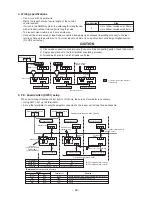
Page 55: ... remote controller only Preparation in advance 1 Push TEST SET CL buttons simultaneously for 4 seconds or more on the remote controller Push buttons while the air conditioner stops The first displayed unit No is the master indoor unit address in the group control 2 Every pushing UNIT button the indoor unit No in the group control is displayed one after the other Select a main indoor unit outdoor u...

Page 56: ...ndoor unit address in the group control In this time fan and louver of the selected indoor unit operate ò 2 Every pushing UNIT LOUVER button button at left side the indoor unit No in the group control is displayed one after the other In this time fan and louver of the selected indoor unit only operate ò 3 Using the set temperature TEMP buttons specify the CODE No DN ò 4 Using the timer time TIME b...

Page 57: ...30 No 30 unit 0001 No 1 unit to 0064 No 64 unit 0000 Individual 0001 Master unit in group 0002 Follower unit in group 0000 0 deg to 0020 20 deg Cool heat are reversed with Data value 2 against the set temperature 0000 None 0001 Provided 0000 Filter input 0001 Alarm input Air cleaner etc 0002 Humidifier input 0000 Indoor thermostat ON 0001 ON receiving output of outdoor compressor 0000 Impossible 0...

Page 58: ...y 2 Use a timer on either Master remote controller or Sub remote controller Terminal block for remote controller cables Remote controller cables Procured locally Indoor unit Outdoor unit Remote controller switch Sub Remote controller switch Master Sold separately 2 1 3 2 1 3 B A B A B A Sold separately 1 2 1 2 1 2 Remote controller Inside of the rear side Sub remote controller Master remote contro...

Page 59: ...ter sign time Indoor discharge temperature 1 Unit C C C C rpm 100h 1h C Outdoor unit data CODE No 60 61 62 63 65 6A 6D 70 72 73 F1 Data name Outdoor heat exchanger Coil temperature TE Outside temperature TO Compressor discharge temperature TD Compressor suction temperature TS Heat sink temperature THS Operation current 1 10 Outdoor heat exchanger Coil temperature TL Compressor operation frequency ...

Page 60: ...e controller The setup range Operation mode Air volume select Setup temp of the indoor unit which was set to the master unit is reflected on the remote controller 1 Concealed duct RAV SMXXXDT is not set up on the master unit If the Concealed duct is the master unit Operation mode Cooling Heating AUTO HEAT COOL FAN and no DRY Air volume select HIGH When the operation mode is DRY FAN stops in duct m...

Page 61: ...struction louver information Remote controller Remote controller operation is available Approx 50 seconds after power ON Regular communication between indoor units Every 30 seconds Header Follower When the above status changes immediately communicates Repetition The unit without power feed waits entirely Waiting status is released by system start Reboot when power is fed on the way 3 minutes elaps...

Page 62: ...he main unit 3 Connect the central control devices to the central control system wiring 4 When controlling DI SDI series only turn on only Bit 1 of SW01 of the least line of the system address No OFF when shipped from the factory In case of DI SDI series the address is necessary to be set up again from the wired remote controller after automatic addressing Indoor units in all refrigerant lines Max...

Page 63: ...ddress SW01 Bit 1 SW01 Bit 2 Remarks 1 ON OFF Turn SW01 Bit 1 to ON 2 OF OFF As status shipped from factory 1 2 3 Refrigerant line 3 1 2 3 A B Reference Setup contents of switch SW01 Bit 1 OFF ON OFF ON Bit 1 OFF OFF ON ON Terminator None 100Ω 75Ω 43Ω Remarks Mixed with multi Link wiring at shipment from factory Central control by digital inverter only Spare Spare Remote controller wiring Central ...

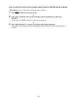
Page 64: ...troller Procedure Perform setup while the unit stops 1 Push TEST VENT buttons for 4 seconds or more When group control is executed first the unit No is displayed and all the indoor units in the group control are selected In this time fans of all the selected indoor units are turned on Fig 1 Keep displayed status without pushing UNIT LOUVER button In case of individual remote controller which is no...

Page 65: ...tton for 4 seconds or more ò 2 In the frame at left side of the remote controller screen the lighting set contents are displayed During unset time At shipment from factory is displayed ò 3 After lighting display for 3 seconds the display automatically disappears If any button is pushed during display immediately the display disappears and then the pushed button is displayed ...

Page 66: ...nd an indoor unit are connected or when an outdoor unit is connected to each indoor unit respectively in the group operation even if multiple refrigerant lines are provided the automatic address setup completes with power ON of the outdoor unit The operation of the remote controller is not accepted while automatic address works Approx 4 to 5 minutes When the following addresses are not stored in t...

Page 67: ...ommunicates serially with the outdoor units The operation mode and setup temperature range are displayed on the remote controller LCD Except air direction adjustment of louver Follower unit 2 Indoor units other than header unit in group operation Basically follower units do not send receive signals to from the remote controllers Except errors and response to demand of service data 10 2 1 System Co...

Page 68: ...ning on source power supply Automatic completion 2 Group operation Multiple outdoor units Multiple indoor units with serial communication only without twin Only turning on source power supply Automatic completion Header Master 1 1 Individual 2 1 Header Sub 1 1 Header Sub 3 1 Header Master 8 1 Header Sub Max 8 units ...

Page 69: ... Controller 1 Push SET CL TEST buttons simultaneously for 4 seconds or more 2 Line address Using the temperature setup buttons set 12 to the CODE No 3 Using timer time buttons set the line address 4 Push SET button OK when display goes on 5 Indoor unit address Using the temperature setup buttons set 13 to the CODE No 6 Using timer time buttons set 1 to the line address 7 Push SET button OK when di...

Page 70: ...identical remote controller Group control unit other unit numbers are also displayed every pushing UNIT LOUVER button 2 To know the position of indoor unit body by address To confirm the unit No in the group control Follow to the procedure during operation in this procedure the indoor units in group control stop Procedure The indoor unit numbers in the group control are successively displayed and ...

Page 71: ...ined and is thus thoroughly acquainted with the knowledge related to this work The qualified installer who is allowed to do the refrigerant handling and piping work involved in installation relocation and removal has the qualifications pertaining to this refrigerant handling and piping work as stipulated by the local laws and regulations and he or she is a person who has been trained in matters re...

Page 72: ...the air conditioner are high voltage areas and rotating parts Due to the danger of electric shocks or of your fingers or physical objects becoming trapped in the rotating parts do not remove the intake grille of the indoor unit or service panel of the outdoor unit When work involving the removal of these parts is required contact a qualified installer or a qualified service person Do not move or r...

Page 73: ...as preserving food precision instruments art objects breeding animals car vessel etc Do not touch any switches with wet finger otherwise you may get an electric shock If the air conditioner will not be used for a considerably long time turn off the main switch or the circuit breaker for safety To make the air conditioner operate in its original performance operate it within the range of the operat...

Page 74: ...ction In the display illustration below all the icons are shown When the unit is in operation only relevant icons will be displayed When turning on the leak breaker at the first time flashes on the display part of the remote controller While this icon is flashing the model is being automatically confirmed Wait till icon has disappeared to use the remote controller 1 Operation mode The selected ope...

Page 75: ...an be operated by pushing the button 1 button Temperature set button Adjusts the set point Select the desired set point by pushing TEMP or TEMP 2 button Timer set button Use to setup the timer 3 button Filter reset button Resets icon after cleaning filter 4 button Test button Use only for service During normal operation do not use this button 5 button When the button is pushed the operation starts...

Page 76: ...ay continue to run for approx 30 seconds When the room temperature reaches the set temperature the outdoor unit stops and the indoor unit will carry on fan operation During defrost operation the fan stops so that cool air is not discharged Pre heat is displayed When restarting the operation after stop When attempting to restart the unit immediately after it was stopped the unit can not start for a...

Page 77: ... after the timer reached the preset time the Repeat Off timer resumes the operation by pushing button and stops the operation after the time of the timer has reached the set time When you push while the Off timer function of the air conditioner is active the indication of the timer function disappears and then appears again after about 5 seconds This is due to normal processing of the remote contr...

Page 78: ...r distribution in the room Checks before operating Check whether the earth wires are properly connected Check whether the air filters are installed Turn on the leakage breaker at least 12 hours before operating Protective device The protective device stops operation when the air conditioner is overloaded When the protective device is activated the current operation stops and the operation lamp and...

Page 79: ...he main power supply to the air conditioner NOTE For environmental conservation it is strongly recommended that the indoor and outdoor units of the air conditioner in use be cleaned and maintained regularly to ensure efficient operation of the air conditioner When the air conditioner is operated for a long time periodic maintenance once a year is recommended Furthermore regularly check the outdoor...

Page 80: ...1 C to 32 C Dry bulb temp 15 C to 24 C Wet bulb temp CAUTION Room relative humidity less than 80 If the air conditioner operates in excess of this figure the surface of the air conditioner may cause dewing Outdoor temperature 20 C to 15 C Wet bulb temp Room temperature 15 C to 28 C Dry bulb temp 11 INSTALLATION Do not install the air conditioner in the following places Do not install the air condi...

Page 81: ...fficiency In defrosting operation both the indoor and outdoor units stop air flow Hiss sound is heard when flow of the refrigerant is changed for defrosting Resultant water of automatic defrosting in heating operation drains from outdoor unit A white mist of chilled air or water is generated from the outdoor unit When the indoor unit in cooling operation or the outdoor unit in defrosting operation...

Page 82: ...g and piping work involved in installation relocation and removal has the qualifications pertaining to this refrigerant handling and piping work as stipulated by the local laws and regulations and he or she is a person who has been trained in matters relating to refrigerant handling and piping work on the air conditioners made by Toshiba Carrier Corporation or alternatively he or she has been inst...

Page 83: ...elmets for use in industry Shoes with additional protective toe cap Gloves to provide protection for electricians and from heat n Warning Indications on the Air Conditioner Unit Warning indication WARNING ELECTRICAL SHOCK HAZARD Disconnect all remote electric power supplies before servicing WARNING Moving parts Do not operate unit with grille removed Stop the unit before the servicing CAUTION High...

Page 84: ...od which may result in refrigerant leakage After the installation work confirm that refrigerant gas does not leak If refrigerant gas leaks into the room and flows near a fire source such as a cooking range noxious gas may be generated When the air conditioner has been installed or relocated follow the instructions in the Installation Manual and purge the air completely so that no gases other than ...

Page 85: ...t and installation tools are changed from those for the conventional refrigerant Accordingly the exclusive tools are required for the new refrigerant R410A For connecting pipes use new and clean piping designed for R410A and please care so that water or dust does not enter To Disconnect the Appliance from Main Power Supply This appliance must be connected to the main power supply by means of a swi...

Page 86: ...the wireless remote controller is used in a room equipped with an inverter type fluorescent light or at a place exposed to direct sunlight signals from the remote controller may not be received correctly Place where organic solvent is used Place where special spray is used frequently n Installation under high humidity atmosphere In some cases including the rainy season especially inside of the cei...

Page 87: ... each other Front view Side view Vinyl hose n Installation of hanging bolt Consider the piping wiring after the unit is hung when determining the location of the indoor unit installation and orientation After the location of the indoor unit installation has been determined install hanging bolts For the dimensions of the hanging bolt pitches refer to the external view When a ceiling already exists ...

Page 88: ...e openings are not adjacent to each other 2 The indoor unit does not have a built in air filter Make sure to set up the filter chamber etc and install the air filter Locally procured If no air filter is installed the heat exchanger will be blocked by dust which may cause the malfunction of air conditioner or the water leakage Duct installation example First floor Duct hose with heat insulation Fle...

Page 89: ...ressure tap 50Hz 4 4 5 5 5 5 6 6 5 7 7 5 8 3000 2800 3400 3800 4200 4400 2880 3200 3600 4000 4320 5 50 100 150 200 250 300 Standard air volume 3600m h High static pressure tap 50Hz Medium static pressure tap 50Hz Low static pressure tap 50Hz Current of fan motor A External static pressure Pa Medium static pressure tap 50Hz Air volume m h High static pressure tap 50Hz Low static pressure tap 50Hz L...

Page 90: ...wiring diagram of the indoor unit is made Terminal block No F1 F2 F3 Fan motor wiring Yellow Low static pressure Blue Middle static pressure Orange High static pressure External static pressure Pa mmAq 69 7 137 14 196 20 Remarks Factory default 6 DRAIN PIPING WORK CAUTION Following the Installation Manual perform the drain piping work that water is properly drained and apply a heat insulation not ...

Page 91: ... time to dry and indurate the adhesive agent Refer to the manual of adhesive agent Do not apply any extra force on the connecting section until the adhesive agent dried n Drain up When install the drain up kit of optional accessory read the Installation Manual supplied to a drain up kit n Check the draining Check if the water can flow out properly during the test run Also check if no water leakage...

Page 92: ...s at intervals of 2 5 to 3 m to clamp the refrigerant pipe Otherwise abnormal sound may be generated CAUTION IMPORTANT 4 POINTS FOR PIPING WORK 1 Remove dust and moisture from the inside of the connecting pipes 2 Tight connection between pipes and unit 3 Evacuate the air in the connecting pipes using VACUUM PUMP 4 Check the gas leakage Connected points n Pipe size n Liquid side refrigerant pipe co...

Page 93: ...nit For details follow to the Installation Manual attached to the outdoor unit Never use the refrigerant sealed in the outdoor unit for evacuation REQUIREMENT For the tools such as charge hose etc use those manufactured exclusively for R410A Outer dia of copper pipe 12 7 mm dia Tightening torque 50 to 62 5 0 to 6 2 kgf m Refrigerant amount to be added For addition of the refrigerant add refrigeran...

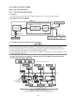
Page 94: ... same line Do not turn on the power of the indoor unit until vacuuming of the refrigerant pipes completes Remote controller wiring 2 core non polarity wire is used for the remote controller wiring Wiring 1 Figure below shows the wiring connections indoor power line and between the indoor and outdoor units and between the indoor units and remote controller The wires indicated by the dash lines are ...

Page 95: ...ailable Approx 5 minutes When power is turned on for the second or later time It takes approx 1 minute until the remote controller becomes available Power on SETTING flashes SETTING goes out Remote controller is available Approx 1 minute Normal settings were made when the indoor unit was shipped from factory Change the indoor unit settings as required Use the wired remote controller to change the ...

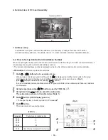
Page 96: ...E buttons Each push of the button changes the power level by 1 within the range from 100 to 50 The factory default is 75 Setting of power level in power saving mode 4 Determine the setting by pushing button 5 Push button to complete the setting n Remote controller switch monitoring function This function is available to call the service monitor mode from the remote controller during a test run to ...

Page 97: ... 1 7 3 3 4 3 3 2 4 2 5 2 5 3 Procedure 1 Push simultaneously buttons for 4 seconds or more After a while the display part flashes as shown below Check the displayed CODE No is 10 When the CODE No is other than 10 push button to erase the display and repeat procedure from the first step After pushing button operation of the remote controller is not accepted for approx 1 minute For a group control N...

Page 98: ... Procedure 2 In the group control every pushing button the indoor UNIT No in the group control is displayed in order In this time the position of the indoor unit can be confirmed because only fan of the selected indoor unit operate For a group control No of the firstly displayed indoor unit becomes the header unit Procedure 3 After confirmation push button to return the mode to the usual mode When...

Page 99: ...nnecting a return air duct to the unit the cleaning method of the air filter differs according to the construction of duct end Ask a qualified installer or qualified service person Daily maintenance Cleaning of air filter 1 If is displayed on the remote controller contact to qualified installer or qualified service person 2 Take out the air filter Push the extrusion of the air filter to inside and...

Page 100: ...firmation and check When an error occurred in the air conditioner an error code and indoor UNIT No appear on the display part of the remote controller The error code is only displayed during the operation If the display disappears operate the air conditioner according to the following Confirmation of error log for confirmation n Confirmation of error log When an error occurred on the air condition...

Page 101: ... Compressor lock was detected Current detect circuit outdoor unit P C board Abnormal current was detected in AC CT or a phase loss was detected Malfunction of the case thermostat Current high pressure switch circuit outdoor P C board Ps pressure sensor error was detected or low pressure protective operation was activated Air conditioner status Auto reset Auto reset Auto reset Auto reset Auto reset...

Page 102: ...en start the work Necessarily put gloves when starting the work Working with the naked hands may cause injury on the hands NOTE Each fan motor weights approx 8 kg An air blower assembly with 1 fan weights approx 20 kg and with 2 fans weights approx 39 kg An air blower assembly can be derived from main unit by one person However the assembly must be carried by two people Air blower assembly 1 fan t...

Page 103: ... parts box cover 2 Remove the electric parts box cover 3 Cut the bundling band 3 positions which binds the fan motor lead wires 4 Remove yellow F1 blue F2 and orange F3 Faston terminals of the fan motor lead wires 5 Remove FAN1 White FAN2 Blue and FAN3 Red connectors of the fan motor 6 Take off screws Arrow mark indicating position of the cabinet M5 screw 8 positions 7 Remove the temperature senso...

Page 104: ...positions M8 screw 2 positions Fan case M8 screw 2 positions A side B side Fan motor earth Ø4 1 position Status when all the fan assemblies are pulled out 12 12 14 14 15 15 15 15 17 17 16 16 12 14 15 15 17 16 18 19 No 1 Part name Fan assembly Continued Work procedure 12 Take off screws Arrow mark indicating position of the fan assembly M5 screw 3 positions 13 Pull out the fan assembly two fans tow...

Page 105: ... status as that before replacement Be careful there is no loosening of screws when assembling Check also that there is no fitting of fan with fan case no air discharge and no abnormal sound Remarks Tightening band Tightening band Ø4 1 position for left right each 4 1 position for left right each Fix the both ends of the Fix the both ends of the protective tube so that it protective tube so that it...

Page 106: ...nual 207 431S8156 Owner s Manual 208 43166011 Remote Controller SX A4EE 209 43166004 Remote Controller SX A11JE2 210 43166012 Remote Controller SX A5EE 211 43177009 Pump Drain PCD 4N230TF 2 230V 50 60Hz 212 43151300 Switch Float FS 0208 603 Model Name RAV SM 2242DT E 2802DT E 2242DT TR 2802DT TR 3 3 3 3 3 3 3 3 3 3 3 3 6 6 6 6 6 6 6 6 1 1 1 1 1 1 1 1 1 1 1 1 1 1 1 1 1 1 1 1 1 1 1 1 211 201 208 209...

Page 107: ...vaporator Ass y 214 4314Q091 Distributor Ass y 215 43047688 Nut Flare 1 2 IN 216 43149332 Socket 217 43147195 Bonnet 1 2 IN 218 43019904 Holder Sensor 219 43147726 Strainer Model Name RAV SM 2242DT E 2802DT E 2242DT TR 2802DT TR 1 1 1 1 1 1 1 1 1 1 1 1 1 1 1 1 1 1 1 1 2 2 2 2 1 1 1 1 ...

Page 108: ...nal Block 2P 20A AC300V 408 43060859 Fuse Block 30A 250V 409 4316V419 P C Board Ass y MCC 1263 410 4316V418 P C Board Ass y MCC 1403 411 4316V247 P C Board Ass y MCC 1520 412 43060157 Terminal Block 4P 413 43160582 Terminal 4P 414 43060700 Fuse 10A 250V Model Name RAV SM 2242DT E 2802DT E 2242DT TR 2802DT TR 3 3 3 3 2 2 2 2 1 1 1 1 2 2 2 2 1 1 1 1 1 1 1 1 1 1 1 1 3 3 3 3 1 1 1 1 1 1 1 1 1 1 1 1 1 ...

Page 109: ...ed by laws to be imposed which protect the ozone layer However since it contains more than air it poses the risk of suffocation if its concentration should rise excessively Suffocation from leakage of R410A is almost non existent With the recent increase in the number of high concentration buildings however the installation of multi air conditioner systems is on the increase because of the need fo...

Page 110: ...TOSHIBA CARRIER CORPORATION 23 17 TAKANAWA 3 CHOME MINATOKU TOKYO 108 8580 JAPAN Copyright 1999 to 2010 TOSHIBA CARRIER CORPORATION ALL Rights Reserved ...

Reviews: