8
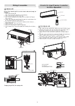
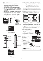
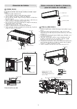
1 Open two screw caps and securely remove two screws at the front panel.
2. Slightly open the lower part of the front panel then pull the upper part of
the front panel toward you to remove it as shown on
fi
gure
1
.
3. Arrange the control wire as detail and speci
fi
cation as shown on
fi
gure
2
.
4. Securely connect the control wire to terminal of Display unit as shown on
fi
gure
3
(tighten
fi
rmly but not over 0.12 N·m (0.01 kgf·m)).
5. Set the control wire out from indoor unit same portion as power supply
and connecting cable as shown on
fi
gure
3
. (Notch for wire out)
6. Reassembly the indoor unit by reverse process of 1 to 2.
Screw
Screw cap
Screw
Front panel
1
2
3
* Wire size 28-22AWG
or 0.08-0.32 mm
2
Outer diameter not over 4.7 mm,
control wire length 30 m. or less.
70 mm
5 mm
Terminal
Control wire
Notch for wire out
Control wire
Display unit
Indoor unit
Control wire
Remote controller
How to Connect Remote Controller
for Wire Operation
For indoor unit
Wiring Connection
Indoor unit
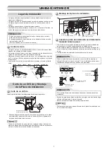
Wiring of the connecting cable can be carried out without removing the
front panel.
1. Remove the air inlet grille.
Open the air inlet grille upward and pull it toward you.
2. Remove the terminal cover and cord clamp.
3. Insert the connecting cable (according to the local cords) into the pipe
hole on the wall.
4. Take out the connecting cable through the cable slot on the rear panel so
that it protrudes about 20 cm from the front.
5. Insert the connecting cable fully into the terminal block and secure it
tightly with screws.
6. Tightening torque : 1.2 N·m (0.12 kgf·m)
7. Secure the connecting cable with the cord clamp.
8. Fix the terminal cover, rear plate bushing and air inlet grille on the indoor
unit.
Cord clamp
Terminal cover
Screw
Screws
Air inlet grille
Front panel
3
Connecting cable connect to
1
2
3
Earth line
50 mm
10 mm
70 mm
10 mm
Earth line
Connecting cable
Terminal block (1 2 3)
Stripping length of the Connecting cable
Summary of Contents for RAS-M05N4KVSG-E
Page 15: ......
Page 30: ......
Page 45: ......
Page 60: ......
Page 61: ...KLIMAGERÄT MULTI TYP INSTALLATIONSHANDBUCH Innengerät RAS M05N4KVSG E R32 DEUTSCH 1126250101 ...
Page 75: ......
Page 90: ......
Page 105: ......
Page 120: ......
Page 135: ......
Page 150: ......
Page 165: ......
Page 180: ......
Page 195: ......
Page 210: ......
Page 225: ......
Page 240: ......
Page 255: ......
Page 270: ......
Page 285: ......
Page 286: ...ÕHUKONDITSIONEER MULTI TYPE PAIGALDUSJUHEND Siseseade RAS M05N4KVSG E R32 EESTI 1126250101 ...
Page 300: ......
Page 315: ......
Page 330: ......
Page 345: ......
Page 360: ......


