


The operating pressure of R32 or R410A
is higher than that of R22 (approx.
1.6 times). It is therefore necessary
to fi rmly tighten the fl are pipe
connecting sections (which connect
the indoor and outdoor units) up to the
specifi ed tightening torque. Incorrect
connections may cause not only a
gas leakage, but also damage to the
refrigeration cycle.
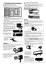
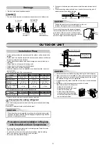
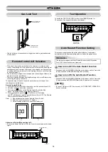
Draining the Water
Holes are provided on the base plate of the outdoor unit to ensure that the
defrost water produced during heating operations is drained off effi ciently.
If a centralized drain is required when installing the unit on a balcony or
wall, follow the steps below to drain off the water.
1. Proceed with water-proofi ng by installing the water-proof rubber caps
in the 2 elongated holes on the base plate of the outdoor unit. [How to
install the water-proof rubber caps]
1) Place four fi ngers into each cap, and insert the caps into the water
drain holes by pushing them into place from the underside of the base
plate.
2) Press down on the outer circumferences of the caps to ensure that
they have been inserted tightly.
(Water leaks may result if the caps have not been inserted properly,
if their outer circumferences lift up or the caps catch on or wedge
against something.)
Water-proof rubber caps
(supplied with the outdoor unit)
Base plate
Drain nipple
2. Install the drain nipple and a commercially available drain hose
(with 16 mm inside diameter), and drain off the water.
(For the position where the drain nipple is installed, refer to the
installation diagram of the indoor and outdoor units.)
Check that the outdoor unit is horizontal, and route the drain hose at a
downward sloped angle while ensuring that it is connected tautly.
Base plate
Drain nipple
Commercially available
drain hose
Do not use ordinary garden hose, but one can flatten and prevent water
from draining.
90
Obliquity
Roughness
Warp
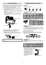
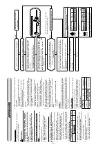
Refrigerant Piping Connection
1. Cut the pipe with a pipe cutter.
2. Insert a fl are nut into the pipe and fl are the pipe.
Projection margin in fl aring : A (Unit : mm)
RIDGID
(clutch type)
Outer dia.
of copper pipe
Conventional tool
used
Ø6.35
0 to 0.5
1.0 to 1.5
Ø9.52
0 to 0.5
1.0 to 1.5
Ø12.70
0 to 0.5
1.0 to 1.5
Pipes thickness
0.8 mm or more
Flaring
Flare nut
Half union
Externally
threaded side
Internally
threaded side
Use a wrench to secure.
Use a torque wrench to tighten.
CAUTION
IMPERIAL
(wing nut type)
Outer dia. of copper pipe
Ø6.35
1.5 to 2.0
Ø9.52
1.5 to 2.0
Ø12.70
2.0 to 2.5
Pipes thickness
0.8 mm or more
Align the centers of the connecting pipes and tighten the fl are nut as far as
possible with your fi ngers. Then tighten the nut with a spanner and torque
wrench as shown in the fi gure.
Tightening connection
Do not apply excess torque. Otherwise, the nut may crack depending on
the conditions.
(Unit : N·m)
Outer dia. of copper pipe
Tightening torque
Ø6.35 mm
16 to 18 (1.6 to 1.8 kgf·m)
Ø9.52 mm
30 to 42 (3.0 to 4.2 kgf·m)
Ø12.70 mm
50 to 62 (5.0 to 6.2 kgf·m)
A
Die
Pipe
Flare at
indoor unit side
Flare at
outdoor unit side
Tightening torque of fl are pipe connections
Do not scratch the inner surface of the fared part when removing burrs.
Flare processing under the condition of scratches on the inner surface of
fare processing part will cause refrigerant gas leak.
CAUTION
R32 tool used
Tool used
10
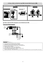
Summary of Contents for RAS-18J2AVSG-E1
Page 20: ...18 ...


