–
3
1
–
VP
Outdoor unit
Charge
hose (B)
Service port
Packed
valve
A
B
C
D
Gas
(
Ø
9,52)
Liquid
(
Ø
6,35)
Indoor unit
Lo
Hi
High pressure
side handle
Pressure gage
Manifold valve
Low pressure side handle
Charge hose (A)
Fig. 8-5-5
CAUTION
•
KEEP IMPORTANT 4 POINTS FOR
INSTALLATION (PIPING WORK)
(1) Take away dust and moisture (Inside of the
connecting pipes.)
(2) Tight connection (between pipes and unit)
(3) Evacuate the air in the connecting pipes using
VACUUM PUMP.
(4) Check gas leak (connected points)
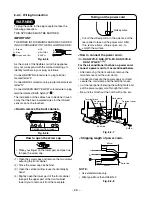
<Packed Valve Handling Precautions>
•
Open the valve stem all the way out; so not try
to open it beyond the stopper.
•
Securely tighten the valve stem cap with the
wrench or like.
•
Valve stem cap tightening torque is as follows;
Gas pipes side (
Ø
9,52) : 30 ~ 42 N
•
m (3,0 ~ 4,2 kgf
•
m)
Liquid pipe side (
Ø
6,35) : 16 ~ 18 N
•
m (1,6 ~ 1,8 kgf
•
m)
Service port cap
: 9 ~ 10 N
•
m (0,9 ~ 1,0 kgf
•
m)
<A5 mm hexagon wrench is required.>
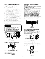
8-5-3. Wiring Connection
(1) Remove the electric parts cover from the outdoor
unit. (1 screw)
(2) Connect the connecting cable to the terminals as
identified with their respective matched numbers
on the terminal block of indoor and outdoor units.
(Strip the sheath of connecting cable with follow-
ing stripping length to and insert into the terminal
block.)
(3) When connect the connecting cable to outdoor
unit terminal, make a loop as shown in the
installation diagram of indoor and outdoor unit, to
prevent water coming in the outdoor unit.
(4) Insulate the unused cords (conductors) with
water coming in the outdoor unit. Process them
so that they do not touch any electrical or metal
parts.
<Stripping length of connecting cable>
60mm
1
1
2
10mm
10mm
50mm
Connecting
cable
Screw
Terminal block
Terminal
screw
Cord clamp
Earth line
2
Earth line
For a three conductor cable
Fig. 8-5-7
CAUTION
•
Wrong wiring connections may cause some
electrical parts to burn out.
•
Be sure to comply with local code on running
the wire from the indoor unit to outdoor unit.
(size of wire and wiring method etc.)
•
Every wire must be connected firmly.
NOTE :
•
Wipe type : More than H05 RN-F
5mm
Flare nut
Stopper
Wrench
Valve body
Valve stem
Service port cap
Service port
Valve stem cap
Note :
Service port at Gas pipes valve only.
Fig. 8-5-6

