12
P9 ASD Quick Start Guide
Connecting the ASD
Refer to the section titled
Installation Precautions on pg. 4
before attempting to connect the ASD and/or the motor to electrical power.
Power Connections
C o n t a c t W i t h 3 - P h a s e I n p u t / O u t p u t T e r m i n a l s M a y C a u s e A n
E l e c t r i c a l S h o c k R e s u l t i n g I n I n j u r y O r L o s s O f L i f e .
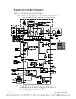
See the
Typical Connection Diagram on pg. 22
for a system I/O connectivity schematic.
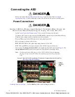
An inductor (DCL) may be connected across the
PO
and
PA/+
terminals to provide additional filtering.
When not used, a jumper must be connected across these terminals.
PA/+
and
PB
are used for the DBR connection if using a braking resistor.
PC/-
is the negative terminal of the DC bus.
R/L1
,
S/L2
, and
T/L3
are the 3-phase input supply terminals for the ASD.
U/T1
,
V
/
T2
, and
W/T3
are the output terminals of the ASD that connect to the motor.
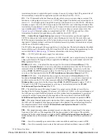
The location of the
Charge Indicator LED
for the smaller typeform ASD is provided in
. The
Charge Indicator LED
is located on the front door of the enclosure of the larger ASDs.
Note:
The Charge Indicator LED shown is of the 1 HP P9 ASD. See the accompanying
drawings of your received P9 ASD for the actual location of the Charge Indicator
LED.
Figure 2. Typical P9 ASD Input/Output Terminals, Charge Indicator LED, and the
DANGER
DANGER
Charge
Indicator
LED
— Pull for
Small
capacitance/push for
Large
capacitance.
Phone: 800.894.0412 - Fax: 888.723.4773 - Web: www .ctiautomation.net - Email: [email protected]


