background image

MR-2012 DISASSEMBLY AND REPLACEMENT

6 - 4

October 2000 © TOSHIBA TEC

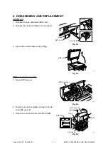
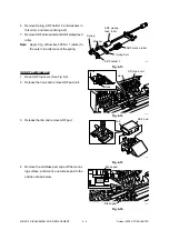
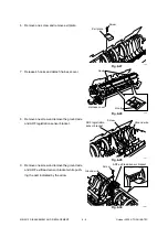
6. Remove Spring, ADF holder F, and washers in

this order, and remove timing belt.

7. Remove ADF pickup roller and ADF pickup feed

roller.

Note:

Apply 0.1g of Sumitec 505 No. 1 (white) to

the outer circumference of the spring.

Fig. 6-13

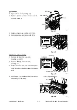
[G] ADF pad/brake pad

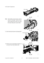
1. Open ADF top cover. (See Fig. 6-3)

2. Release the hook and remove ADF pad unit.

Fig. 6-14

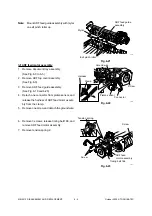
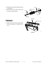
3. Release the tab and remove ADF pad.

Fig. 6-15

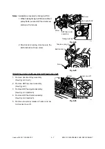
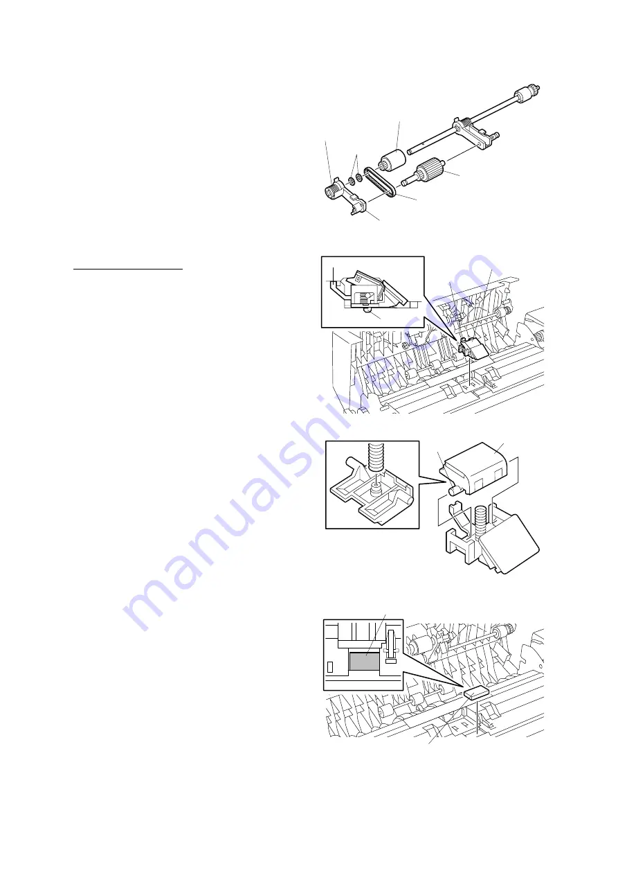
4. Remove the old brake pad, wipe off the mount-

ing surface, and mount a new brake pad to the

position shown below.

Fig. 6-16

ADF pickup
feed roller

Spring

Washer

ADF pickup roller

Timing belt

ADF holder F

Hook

Hook

Hook

ADU pad unit

Tab

ADF pad

Brake pad

Brake pad

172

173

174

175

Summary of Contents for MR-2012

Page 1: ...AUTOMATIC DOCUMENT FEEDER MR 2012 File No 31100013 ...

Page 2: ...Basically the machine should not be operated with any parts removed or disassembled 7 Delicate parts for preventing safety hazard problems such as breakers thermofuses fuses door switches sensors etc if any should be handled installed adjusted correctly 8 Use suitable measuring instruments and tools 9 During servicing or maintenance work be sure to check the serial No plate and other cautionary la...

Page 3: ...r jam detection 3 2 3 3 3 ADF registration sensor stay jam detection 3 2 3 3 4 ADF read sensor unreached jam detection 3 2 3 3 5 ADF read sensor stay jam detection 3 2 3 3 6 ADF exit sensor unreached jam detection 3 2 3 4 Flow Chart 3 3 4 MECHANICAL DESCRIPTION 4 1 4 1 Paper Feed System 4 1 4 2 Document Size Detection Method 4 2 4 3 Drive System 4 4 5 CIRCUIT DESCRIPTION 5 1 5 1 PWA Block Diagram ...

Page 4: ...FICATIONS 1 SPECIFICATIONS Function Auto document feeder No of originals loaded Max 50 originals A4 60 to 80g m2 Document size A5 R Min to A3 Max Dimensions 530 W x 450 D x 120 H mm Weight Approx 5 4 kg Power supply 5V 24V Supplied from copier ...

Page 5: ...October 2000 TOSHIBA TEC 2 1 MR 2012 OUTLINE 2 OUTLINE 2 1 Names of Various Components Connection Cable ADF 02 01 01 ADF top cover Document guide R Document tray Document guide F ...

Page 6: ...MR 2012 OUTLINE 2 2 October 2000 TOSHIBA TEC 2 2 Layout of Electrical Parts VR1 SW1 SEN1 SEN5 SEN4 SEN6 SEN3 SEN2 ADF 02 02 01 M1 ADF PWA ADF 02 02 02 ...

Page 7: ...sensor ADF PWA ADF MOT ADF motor Function Detects the open close state of the top cover during jamming processing etc Detects the width of document Detects the open close state of the ADF unit Detects the length of document Detects the loading of document Detects the aligning position of document Detects the document scanning start position Detects the ejection of document PWA which relays the sen...

Page 8: ... 1 2 3 4 5 6 7 8 9 10 11 12 13 14 15 16 17 18 19 20 NC NC NC NC NC CN1 SG HAI 5V HAISI 1 2 3 ADF top cover open switch ADF exit sensor 3 2 1 N C N O COM CN11 CN10 CN9 CN6 CN12 POS 5V D A 4 5 6 ADF read sensor 3 2 1 SG REG 5V REGST 7 8 9 ADF registration sensor 3 2 1 SG EMP 5V EMPTY 10 11 12 Document empty sensor 3 2 1 SG OPN 5V DF_OPN 13 14 15 ADF open sensor 3 2 1 CN12 Document length sensor 3 2 ...

Page 9: ...October 2000 TOSHIBA TEC 2 5 MR 2012 OUTLINE 2 4 Board Assembly ADF 02 04 01 ...

Page 10: ...ument transport sensors to detect the position of document etc and a motor for transport It also has one PWA where comparator IC s only are installed and the other signals simply pass For this reason all control and processing are performed by the scanner PWA 3 2 Block Diagram ADF 03 02 01 ADF PWA ADF CN6 CN1 Scanner PWA ADF read sensor ADF open cover sensor Document length sensor Document width s...

Page 11: ... will be detected 3 3 4 ADF read sensor unreached jam detection The number of pulses time equivalent to the distance from the ADF registration sensor to the ADF read sensor plus 30 mm is regarded as timing for detecting a jam When the time from the moment of starting the transport of the document having reached the ADF registration sensor to the moment when the ADF read sensor is turned ON exceeds...

Page 12: ...October 2000 TOSHIBA TEC 3 3 MR 2012 OPERATIONAL DESCRIPTION 3 4 Flow Chart Start button ON End Document feed from ADF YES Scanning of final document Scanning of document Cassette feed Copy Ejection NO ...

Page 13: ...are separated by the separation pad under the feed roller and transported one by one The document driven by the feed roller is then transported by the read roller There the transport of the document is detected by the ADF registration sensor When the top of the paper reaches the ADF read sensor the scanner starts scanning The scanned document passes over the ADF exit sensor as driven by the read r...

Page 14: ...e ADF is on standby or the document empty sensor is ON the document width sensor is checked every 100 ms and the value obtained is compared with that of the last time If the value is found changed as a result of the comparison the document size will be detected and sent to the copier when in ADF active mode When this unit receives a command accompanied by a document size notice request from the co...

Page 15: ...N LT series Document width Document length sensor 1 OFF ON 129 40 177 99 STR 139 7 x 215 9 178 00 236 99 LTR 215 9 x 279 4 LG 215 9 x 355 6 237 00 268 99 COMPUTER 257 2 x 356 269 00 310 00 LT 279 4 x 215 9 LD 279 4 x 431 8 1 ON for a document length of 306 mm ...

Page 16: ... direction counterclockwise for rotation Document Feed The document is fed as the ADF motor turns clockwise as viewed from the front in the direction of the black arrow When the ADF motor turns clockwise the pickup roller lowers to pull in the document At this time the read roller does not turn due to the function of the one way clutch DocumentTransport The document is transported as the ADF motor...

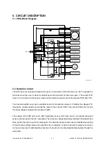
Page 17: ...t length sensor each are input to the IC1 comparator The reference voltage obtained by dividing 5V though R2 and R4 is input to the other input of the comparator The detection level of each sensor is stabilized according to this reference voltage value and output from the comparator Since the document empty sensor does not require accuracy for detecting the presence of a document its output signal...

Page 18: ...document present photoelectric current flowing through PTr increases and a drop in voltage due to R17 causes the voltage at pin 6 of IC8 to rise IC8 is a comparator which compares the reference voltage input to pin 5 non inverting input with the signal voltage at pin 6 inverting input When the voltage at pin 6 is higher the output pin 7 of IC8 turns to Low level Conversely when a quantity of light...

Page 19: ...to a certain voltage through the resistor and capacitor The voltage is input to IC10 pins 3 and 14 to set the current value for the motor The current value for the motor can be set as desired by changing the duty of the PWM signal AENB is a signal to control the output of the motor driver When the signal is at High level the output of the driver becomes effective IC1 Scanner MPU IC4 Motor control ...

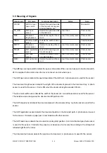
Page 20: ... other sensors The ADF read sensor detects the document scanning start position A mirror reflective type photo sensor is used for the sensor It detects the presence or absence of a document according to the strength of reflected light from the mirror The document exit sensor detects the ejection of a document A photo sensor is used for the sensor Signal name COVER DF_OPN SIZE WIDTH EMPTY REGST POS...

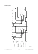
Page 21: ...PTION 5 6 Timing Chart OFF ADF motor OFF Document empty sensor OFF OFF ADF registration sensor ADF read sensor OFF ADF exit sensor ON ON ON ON Forward Reverse Pre feed Paper feed Scan Eject 1 8 8 10 10 9 9 11 12 13 14 11 3 4 5 1 3 4 5 6 2 2 ADF 05 06 01 ...

Page 22: ... and detach one connector Fig 6 1 3 Open ADF unit and take it out by lifting Fig 6 2 B Document tray assembly 1 Open ADF top cover Fig 6 3 2 Remove one screw release 3 hooks and de tach ADF cover R 3 Detach one connector from ADF PWA CN5 Fig 6 4 Clamp Hook ADF cover Connector ADF unit ADF top cover ADF cover R Screw Hook ADF PWA CN5 Connector Hook 160 161 162 163 ...

Page 23: ...nd 6 2 2 Remove document tray assembly See Fig 6 3 to 6 5 3 Detach document tray cover See Fig 6 6 4 Release the harness from the clamp and de tach the document length sensor harness 5 Remove one screw release the hook and re move document width sensor assembly Fig 6 7 Notes 1 Align the arrow mark of sensor holder with that of document guide gear 2 Align the cut part of document guide rack with th...

Page 24: ... top cover See Fig 6 3 2 Remove 2 screws and remove ADF document guide Fig 6 10 3 Remove two each of stop ring and bushing and remove ADF pickup roller assembly Fig 6 11 4 Detach 2 stop rings and remove shutter stop per 5 Slide ADF holder F in the direction of the arrow and draw out pin Fig 6 12 Stop ring ADF top cover assembly Stop ring ADF document guide Screw Stop ring Bushing Stop ring ADF pic...

Page 25: ...mference of the spring Fig 6 13 G ADF pad brake pad 1 Open ADF top cover See Fig 6 3 2 Release the hook and remove ADF pad unit Fig 6 14 3 Release the tab and remove ADF pad Fig 6 15 4 Remove the old brake pad wipe off the mount ing surface and mount a new brake pad to the position shown below Fig 6 16 ADF pickup feed roller Spring Washer ADF pickup roller Timing belt ADF holder F Hook Hook Hook A...

Page 26: ... 18 I ADF feed guide assembly 1 Remove document tray assembly See Fig 6 3 to 6 5 2 Remove ADF top cover assembly See Fig 6 9 3 Detach the connectors from ADF PWA CN2 CN4 remove one screw and detach the ground wire Fig 6 19 4 Remove 4 screws release 2 hooks and remove ADF feed guide assembly Fig 6 20 Screw Hook ADF cover R Hook ADF PWA Screw Screw Ground wire ADF PWA Connector ADF feed guide assemb...

Page 27: ... assembly See Fig 6 19 and 6 20 4 Detach one connector from platen sensor and release the harness of ADF feed motor assem bly from the clamp 5 Remove one screw and detach the ground wire Fig 6 22 6 Remove 3 screws release timing belt 166 and remove ADF feed motor assembly 7 Remove tension spring 2 Fig 6 23 ADF feed guide assembly Mylar Exit pinch roller Ground wire Screw Connector Platen sensor Ha...

Page 28: ... screw Fig 6 25 K ADF feed roller shaft assembly ADF feed roller shaft 1 Remove document tray assembly See Fig 6 3 to 6 5 2 Remove ADF top cover assembly See Fig 6 9 3 Remove ADF feed guide assembly See Fig 6 19 and 6 20 4 Remove ADF feed motor assembly See Fig 6 22 and 6 23 5 Remove one screw release 2 hooks and de tach sensor cover R Fig 6 26 Screw Feed pully M 66 Timing belt 166 ADF feed motor ...

Page 29: ...ve one screw and remove the ground wire and ADF registration sensor bracket Fig 6 29 9 Remove one screw and remove the ground wire and ADF exit read sensor bracket while push ing the part indicated by the arrow Fig 6 30 Exit plate Screw Hook Hook Screw ADF registration sensor bracket Ground wire Screw ADF exit read sensor bracket Ground wire 185 186 187 188 1 Harness cover ...

Page 30: ... the mylar sheet by holding it to the two ends Attach the sheet securely with no portion lifted Fig 6 32 11 Detach the E ring and remove feed pulley M 66 Fig 6 33 12 Detach the E ring slide bearing inwards and remove ADF feed roller shaft assembly Fig 6 34 Mylar sheet Mylar sheet Feed pulley M 66 E ring Bearing E ring ADF feed roller shaft assembly Bearing 188 2 188 3 189 190 ...

Page 31: ...ng 14 Detach ADF knob from ADF feed roller shaft and remove bearing and spring Fig 6 35 L ADF front cover 1 Open ADF unit 2 Release 3 screws and hook and detach ADF front cover by sliding it in the direction of the arrow ADF feed roller shaft E ring Spring Bearing Jam dial E ring Bearing Screw ADF front cover 191 1 191 2 Fig 6 36 ...

Page 32: ...1 1 KANDA NISHIKI CHO CHIYODA KU TOKYO 101 8842 JAPAN ...

Reviews: