– 85 –
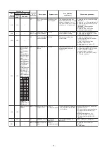
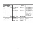
CODE No. (DN)
01
Item
Table 1. Setting data (CODE No. table (example))
Table 2. Type: CODE No. 10
Table 3.
Indoor unit capacity: CODE No. 11
Setting data
Factory-set value
Filter sign lighting time
Depending on Type
02
Filter pollution level
0000: standard
03
Central control address
0099: Not determined
0F
Cooling only
0000: Heat pump
10
Type
Depending on model type
11
Indoor unit capacity
Depending on capacity type
12
System address
0099: Not determined
13
Indoor unit address
0099: Not determined
14
Group address
0099: Not determined
19
Louver type (wind direction adjustment)
Depending on Type.
28
Power failure automatic recovery
0000: None
31
Ventilation fan (standalone)
0000: Not available
32
Sensor SW (Selection of static pressure)
0000: Body sensor
60
Timer setting (wired remote controller)
0000: Available
d0
Remote controller operation save function
0001: Enable
F6
Presence of Application control kit
0000: None
2b
Thermo output SW (T10
e
)
0000: Thermo ON
1E
Temperature range of cooling/heating
automatic SW control point
0003: 3 deg (Ts ±1.5)
C2
Demand setting
(outdoor unit current demand)
0075: 75 %
06
Heating suction temperature shift
0002: +2 ˚C
(flooring installation type: 0)
* EEPROM initial value on the P.C. board for indoor
unit servicing.
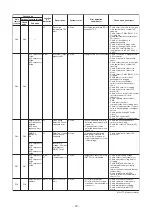
Setting data
Setting data
Model
Setting data
Model
Type
Model abb. name
0013
Floor Standing
MMF-AP
∗∗∗
H
∗
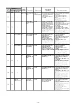
0000*
0001
0002
0003
0004
0005
0006
0007
0008
0009
0010
0011
0012
0013
0014
0015
Invalid
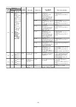
007 type
—
009 type
—
012 type
—
015 type
—
018 type
—
024 type
027 type
030 type
—
036 type
0016
0017
0018
0019
0020
0021
0022
0023
0024
0025
0026
0027
0028
~
0034
—
048 type
056 type
—
—
072 ype
—
096 type
—
—
—
—
—
—
—

