– 70 –
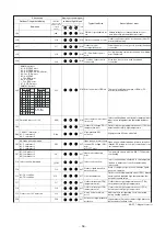
Check code
Location
of
detection
Description
System status
Error detection
condition(s)
Check items (locations)
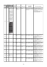
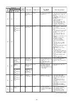
H16
H16
SMMS-i
(4 series)
01: TK1 oil
circuit error
02: TK2 oil
circuit error
03: TK3 oil
circuit error
04: TK4 oil
circuit error
05: TK5 oil
circuit error
I/F
Oil level detection
circuit error
All stop
No temperature change is
detected by TK4 despite
compressor having been
started.
• Check for disconnection of TK4
sensor.
• Check resistance characteristics of
TK4 sensor.
• Check for connection error involving
TK1, TK2, TK3, TK4, and TK5
sensors
• Check for faulty operation in SV3E
or SV3F valve.
• Check for clogging in oil equalizing
circuit capillary and faulty operation
in check valve.
• Check for refrigerant entrapment
inside compressor.
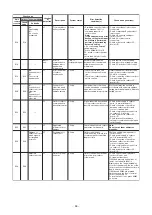
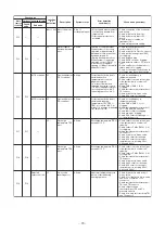
H25
H25
—
I/F
TD3 sensor
miswiring
(incomplete
insertion)
All stop
Air discharge temperature
(TD3) does not increase
despite compressor 3 being in
operation.
• Check installation of TD3 sensor.
• Check connection of TD3 sensor
connector and wiring.
• Check resistance characteristics of
TD3 sensor.
• Check for defect in outdoor P.C.
board (I/F).
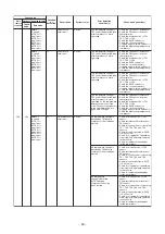
L02
L02
—
Indoor unit Outdoor unit
model mismatch
error
Only the target
unit stopped
An error was found on the
outdoor unit model.
• Check the model name of the
outdoor unit.
• Check the miswiring of the
communication line between indoor
and outdoor.
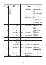
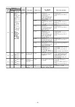
L03
—
—
Indoor unit Duplicated indoor
header unit
Stop of
corresponding unit
There is more than one
header unit in group.
• Check indoor addresses.
• Check for any change made to
remote controller connection
(group / individual) since indoor
address setting.
L04
L04
—
I/F
Duplicated
outdoor line
address
All stop
There is duplication in line
address setting for outdoor
units belonging to different
refrigerant piping systems.
• Check line addresses.
L06
L06
No. of priority
indoor units
I/F
Duplicated priority
indoor unit (as
displayed on
indoor unit other
than priority indoor
unit)
All stop
More than one indoor unit
have been set up as priority
indoor unit.
• Check displays on priority indoor
unit and outdoor unit.
L07
—
—
Indoor unit Connection of
group control
cable to
standalone indoor
unit
Stop of
corresponding unit
There is at least one stand-
alone indoor unit to which
group control cable is
connected.
• Check indoor addresses.
L08
L08
—
Indoor unit Indoor group /
addresses not set
Stop of
corresponding unit
Address setting has not been
performed for indoor units.
• Check indoor addresses.
Note:
This code is displayed when
power is turned on for the first
time after installation.
L09
—
—
Indoor unit Indoor capacity
not set
Stop of
corresponding unit
Capacity setting has not been
performed for indoor unit.
Set indoor capacity. (DN = 11)
L10
L10
—
I/F
Outdoor capacity
not set
All stop
Jumper wire provided on P.C.
board for servicing I/F P.C.
board has not been removed
as required for given model.
Check model setting of P.C. board for
servicing outdoor I/F P.C. board.
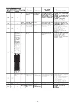
L17
L17
Target indoor
address
I/F
Outdoor unit
model mismatch
error
The outdoor unit model is
duplicate. The Cool/Heat
Flex series 1/2 are duplicate.
• Check the outdoor unit model.
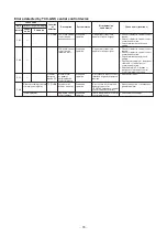
L05
—
—
I/F
Duplicated priority
indoor unit (as
displayed on
priority indoor unit)
All stop
More than one indoor unit has
been set up as priority indoor
unit.
• Check display on priority indoor unit.
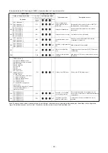
No temperature change is
detected by TK5 despite
compressor having been
started.
• Check for disconnection of TK5
sensor.
• Check resistance characteristics of
TK5 sensor.
• Check for connection error involving
TK1, TK2, TK3, TK4, and TK5
sensors
• Check for faulty operation in SV3E
valve.
• Check for clogging in oil equalizing
circuit capillary and faulty operation
in check valve.
• Check for refrigerant entrapment
inside compressor.
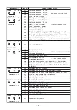
Outdoor 7-segment display
Check
code
Sub-code
Main
remote
controller

