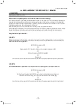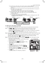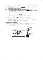
– 95 –
FILE NO. SVM-13085
No.
Part name
Procedure
Remarks
Under panel
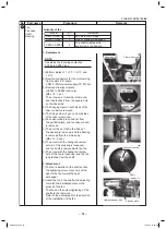
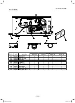
1. Detachment
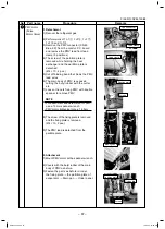
1) Perform works of 1 of .
2) Remove the support plate.
(AP024 to AP056 type only) (Ø4 x 10, 1 pc.)
The screw on a front side is removed,
and it detaches it from the square
hole on the back side.
3) The screw on both sides is removed.
(Ø4 x 10, 2 pcs.)
4) The screw on fan side is removed.
AP015 to AP027 type : (Ø4 x 10, 3 pcs.)
AP036 to AP056 type : (Ø4 x 10, 4 pcs.)
5) Slide to the air discharge side and
remove the under panel.
NOTE
When you remove forcibly which
may result in the product breaks.
6) When you remove the signal receiving
unit, lap the end of flat head screw
driver with vinyl tape, and forcedly
insert it into the groove at the side
under circle mark on the cover.
2. Attachment
1) Attach the under panel from air
discharge side according to drain pan.
2) Attach the screws as original position.
80-160 type attach the support plate as
original position.
8
7
Square hole
Front side screw
Support plate
Screws
Screws
Screws
Vinyl tape
Cover
Insert it into groove at
the side under circle
mark on the cover.
Flat blade screwdriver
(Lap it with vinyl tape.)
SVM-13085.indb 95
SVM-13085.indb 95
12/24/13 10:56 AM
12/24/13 10:56 AM


