– 91 –
FILE NO. SVM-13085
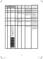
No.
Part name
Procedure
Remarks
Fan,
Fan case,
Quantity of fan
Shaft,
Bearing
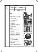
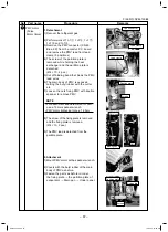
1. Detachment
NOTE
It explains the following content by
AP036 to AP056 type.
2. Attachment
1) The fan is installed in the shaft so that
the tightening screw may come at the
right of the fan toward the heat
exchanger.
2) Insert the fan in the shaft while adjusting
to match the installation mark to the
groove of the fan.
The fan and the screw tightening of the
shaft are the last work.
Refer to the photograph for the direction
of the installation of the fan.
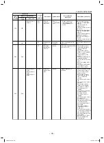
Model
QTY
Installation
AP015, AP018
2
Fan motor both sides
AP024, AP027
3
One of shafts are bearings.
AP036, AP056
4
The shaft middle part is
supported in the bearing.
5
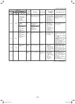
Hanging claw
Bolt
Groove of the fan
Heat exchanger side
Partition plate
Shaft
Square hole
Front side screw
Support plate
Fixing screw
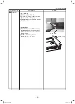
1) Perform works of 1 of
1
, 1 of
2
and
1 of
3
.
2) Remove connectors for fan motor wiring
from control P.C. board.
CN210 : Motor power supply (7P: White)
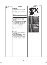
3) Remove the support plate
(AP024 to AP056 type only)
(Ø4 x 10, 1 pc.)
The screw on a front side is removed,
and it detaches it from the square hole
on the back side.
4) The hanging claw on both sides of fan
case (under) is removed.
5) The fixing screw (2 pcs.) on both sides
of fancase is removed.
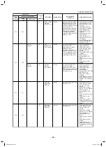
6) Fan case (under) is pulled out from
the partition plate, and fan case (under)
is removed.
7) The bolt (2 pcs.) that is the fixing of
the bearing is removed, and the bearing
is removed from the main body.
(Ø8 x 15, 2 pcs.)
8) The screw with the hexagonal screw
hole to of the coupling is loosened,
and the shaft is removed with the fan.
9) The screw with the hexagonal screw
hole of the fan is loosened, and the fan
is detached from the shaft.
SVM-13085.indb 91
SVM-13085.indb 91
12/24/13 10:56 AM
12/24/13 10:56 AM

