background image


65

ICC 


Supports unconnected messages (UCMM), and up to 16 simultaneous 
class 1 (I/O) or class 3 (explicit) connections. 


Assembly instances 100 and 150:  if a register entry in the consumed data 
configuration array is 0, then any consumed data that corresponds to that 
location will be ignored.  Conversely, if a register entry in the produced 
data configuration array is 0, then any produced data that corresponds to 
that location will be a default value of 0.  Refer to section 10.8.4 for further 
information on the data configuration arrays. 


Point-to-point class 1 connected messages will be produced targeting the 
IP address of the device that instantiated the connection, port 0x08AE (port 
2222). 


If a class 1 connection’s consuming half (O

T) times out, then the 

producing half (T

O) will also time-out and will stop producing. 


If a class 1 or class 3 connection timeout occurs, the driver will trigger a 
timeout event as described in section 10.7.4. 


13.2.2


ODVA AC/DC Drive Profile 

The interface card supports the ODVA AC/DC drive profile.  No special 
Ethernet/IP configuration of the interface card is required when using the 
AC/DC drive profile: all that is needed is that the controller must target either 
assembly instances 20 & 70 or 21 & 71 in its connection parameters. 
 
The AC/DC drive profile 
implementation provides 
support for several 
required CIP objects, 
which are specified in 
Table 3.  While the 
various supported 
attributes of all of these 
objects are accessible via 
explicit messaging, the 
main intent of using the AC/DC drive profile is to interact with the predefined 
input and output assembly instances via an I/O connection.  The structure of 
these assembly instances is defined by the Ethernet/IP specification in order to 
engender interoperability among different vendor’s products.  This section will 
focus primarily on the format of the AC/DC drive profile I/O assemblies 
supported by the interface card, and the inverter data which their various 
constituent elements map to. 

Table 3: AC/DC Drive Profile-Related Objects 

Class Code 

Object Name 

0x04 Assembly 

Object 

0x28 

Motor Data Object 

0x29 

Control Supervisor Object 

0x2A 

AC Drive Object 

Summary of Contents for ICC Multiprotocol Ethernet Interface ASD-G9ETH

Page 1: ...Suite 212 Middleton WI USA 53562 4720 Cypress TX USA 77429 8364 Tel 608 831 1255 Fax 608 831 2045 http www iccdesigns com Printed in U S A ASD INTERFACE SERIES ICC INDUSTRIAL CONTROL COMMUNICATIONS INC ASD G9ETH MULTIPROTOCOL ETHERNET INTERFACE FOR TOSHIBA G9 VFAS1 ADJUSTABLE SPEED DRIVES August 2008 ICC 10639 2 100 000 ...

Page 2: ...ct Bugs may always be present in a system of any size In order to prevent danger to life or property it is the responsibility of the system designer to incorporate redundant protective mechanisms appropriate to the risk involved This user s manual may not cover all of the variations of interface applications nor may it provide information on every possible contingency concerning installation progr...

Page 3: ...tting cabling such as ASD input output power wiring Installation and Wiring Do not touch charged parts of the drive such as the terminal block while the drive s CHARGE lamp is lit A charge will still be present in the drive s internal electrolytic capacitors and therefore touching these areas may result in an electrical shock Always turn the drive s input power supply OFF and wait at least 5 minut...

Page 4: ... 14 5 2 Installing Multiple Option Cards 16 6 LED Indicators 17 6 1 Front Panel 17 6 2 Ethernet Jack 18 7 Configuring the IP Address 19 7 1 Via the Finder Utility 19 7 2 Via the Drive s Keypad 20 7 3 Via the Web Page 20 8 Using the ICC Finder Utility 21 9 Parameter Numbering 22 10 Embedded Web Server 24 10 1 Overview 24 10 2 Authentication 25 10 3 Page Select Tabs 26 10 4 Monitor Tab 26 10 4 1 Inf...

Page 5: ...6 MAC Address Configuration 38 10 7 7 Submitting Changes 38 10 8 EtherNet IP Tab 40 10 8 1 Information Window 40 10 8 2 Device Identification 41 10 8 3 Run Idle Flag Behavior 41 10 8 4 Class 1 I O Data Configuration Arrays 42 10 8 5 Submitting Changes 43 10 9 Alarm Tab 44 10 9 1 Information Window 44 10 9 2 Email Configuration 45 10 9 3 Alarm Configuration 46 10 9 4 Submitting Changes 48 10 10 Mod...

Page 6: ... 13 2 7 ControlLogix Example Read a Single Register 82 13 2 8 ControlLogix Example Multiple MSG Instructions 82 13 2 9 ControlLogix Example Reading and Writing 83 13 3 PCCC 85 13 3 1 Tag Reference 85 13 3 2 SLC 5 05 Example Read a Register Block 86 13 3 3 SLC 5 05 Example Read a Single Register 92 13 3 4 SLC 5 05 Example Multiple MSG Instructions 92 13 3 5 SLC 5 05 Example Reading and Writing 93 1...

Page 7: ... reference or unit inspection For the latest information support software and firmware releases please visit http www iccdesigns com Before continuing please take a moment to ensure that you have received all materials shipped with your kit These items are Ethernet interface in plastic housing Documentation CD ROM Note that different interface firmware versions may provide varying levels of suppor...

Page 8: ...st version of Macromedia Flash Player browser plug in is required Refer to section 9 XML Configuration File Upload Download All interface configuration files are stored in the unit s internal filesystem in XML format These files can be transferred to from a PC via the FTP protocol which provides the capability for PC based file backup and easy configuration copying to multiple units Configuration ...

Page 9: ... the field by the end user Refer to section 12 for more information EtherNet IP Data Access Options The EtherNet IP protocol provides access to inverter data via explicit messaging user defined I O assembly instances and the ODVA AC DC drive profile Refer to section 13 2 for more information ...

Page 10: ...d Health Administration and any other applicable national regional or industry codes and standards DO NOT install operate perform maintenance or dispose of this equipment until you have read and understood all of the following product warnings and user directions Failure to do so may result in equipment damage operator injury or death 3 1 Installation Precautions Use lockout tagout procedures on t...

Page 11: ...al charge for a while after turning supply power off After turning supply power off wait at least ten minutes before servicing the ASD or interface board Ensure that the Charge LED is off prior to beginning maintenance Do Not attempt to disassemble modify or repair the interface board Contact your ICC or Toshiba sales representative for repair or service information Turn the power on only after at...

Page 12: ...es high humidity dust or metal particles 3 5 Warranty This communication interface is covered under warranty by ICC Inc for a period of 12 months from the date of installation but not to exceed 18 months from the date of shipment from the factory For further warranty or service information please contact Industrial Control Communications Inc or your local distributor 3 6 Disposal Contact the local...

Page 13: ...ve explosive gasses Operating Temperature 10 50 C 14 122 F Storage Temperature 40 85 C 40 185 F Relative Humidity 20 90 without condensation Vibration 5 9m s 2 0 6G or less 10 55Hz Grounding Non isolated referenced to ASD control power ground Cooling Method Self cooled Communication Speed 10 100BaseT auto sensing The ASD G9ETH interface is lead free RoHS compliant ...

Page 14: ...erview Mounting Tabs Drive Connector LEDs Ground Plate Configuration Switches Shielded RJ45 Ethernet Jack MAC ID Note The configuration switches are used for factory test only and should remain in the OFF up position at all times ...

Page 15: ...and are locked and tagged out 2 DANGER Wait at least 5 minutes for the drive s electrolytic capacitors to discharge before proceeding to the next step Do not touch any internal parts with power applied to the drive or for at least 5 minutes after power to the drive has been removed A hazard exists temporarily for electrical shock even if the source power has been removed Verify that the CHARGE LED...

Page 16: ...to place Figure 3 Double check that the plastic bosses located on the left and right side of the drive enclosure are properly inserted into the corresponding recesses on the back of the interface housing and that the interface housing is overall secure and flush with the drive enclosure Figure 3 Installing the Interface Card 5 Reinstall the drive s front cover by inserting the tabs on the bottom p...

Page 17: ...uch as drive s input power or motor wiring Also take care to route the cable away from any sharp edges or positions where it may be pinched 7 Turn the power source to the drive ON and verify that it functions properly If the drive does not appear to power up or does not function properly immediately turn power OFF Repeat steps 1 and 2 to remove all power from the drive Then verify all connections ...

Page 18: ...ks followed by 3s of OFF time indicates the error code EIP Module Status Reserved When the multi protocol firmware image with EtherNet IP support is loaded this LED conforms to the prescribed module status LED behavior as dictated in the EtherNet IP specification Volume 2 Chapter 9 When the Profinet IO firmware image is loaded this LED is reserved and therefore always OFF Interface Status 2 1 EIP ...

Page 19: ...hed a link with the interface board and is communicating with it Ethernet Activity Blinks green briefly when network packets are sent or received Heartbeat Blinks green to indicate communication between the interface card and the drive Contact ICC technical support if a blinking red error code is observed 6 2 Ethernet Jack The Ethernet jack also contains two embedded LEDs Reserved Ethernet Link Et...

Page 20: ...ly power to the ASD When the interface boots up it will attempt to obtain an IP address from a DHCP server or failing that will fallback to either the last static IP address assigned or a default static IP address of 192 168 16 102 if no static IP address has yet been assigned 2 To determine the initial IP address of your interface start the ICC FINDER EXE discovery utility 3 The discovery utility...

Page 21: ...mware V203R5 and later and H9 drive control board firmware V204R4 drives only The interface card s IP Address Subnet Mask Default Gateway and DHCP Static IP mode can be viewed and modified via the drive s keypad by navigating to Program Communications Ethernet Settings Additionally the interface card s unique MAC ID can be viewed but not modified in this screen Note that these parameter values are...

Page 22: ...lowing actions Open Web Interface Opens a web browser page of the selected device Refer to section 9 Open FTP Interface Opens the computer s default FTP application which could be either Windows Explorer a web browser or a 3 rd party FTP program whatever the computer operating system is configured for by default This allows you to interact directly with the unit s on board flash filesystem enablin...

Page 23: ...0 FA00 FA99 1001 1100 FB00 FB99 1101 1200 FC00 FC99 1201 1300 FD00 FD99 1301 1400 FE00 FE99 1401 1500 This mapping is easier to understand if one just uses the interface s web page as a guide refer to Figure 6 and section 10 4 4 The parameter numbers ASD references and register numbers network references for all available parameters are shown in the first two columns Commanding the drive over the ...

Page 24: ...he drive In other words if a read from or write to a register that does not correspond to an existing drive parameter takes place the read write will be successful but the data will have no meaning This feature is beneficial in situations where the accessing of non contiguous registers can be made more efficient by accessing an all inclusive block of registers some of which correspond to drive par...

Page 25: ... already installed on your computer then your browser will automatically be redirected to the appropriate Adobe download web site when you initially attempt to access the interface s web page Alternatively the plug in can be downloaded directly by going to http www adobe com and choosing the get Adobe Flash Player link Always ensure that you have the latest version of the Flash Player installed if...

Page 26: ...ked by a firewall or Ethernet router situated between the client computer and the interface card 10 2 Authentication For security the interface requires valid user authentication whenever the web page is accessed The authentication request will appear as a browser popup box that will request entry of a user name and password Refer to Figure 8 Figure 8 Web Server Authentication The factory default ...

Page 27: ... in the upper right hand corner of the monitor tab This window displays various informational messages regarding the status of the interface card or web browser session There is also an activity indicator located in the lower right hand corner of the Information Window which blinks periodically to show the status of data communication between the web browser and the interface card If you do not ob...

Page 28: ...arameters that are identified as being for the internal option board can be used to actually control the drive via the option board all other drive command parameters can only be monitored via the option board Monitor Parameters Only drive monitor parameters are available 10 4 3 Parameter Subgroup Selection List Subgroups can be used to further filter the parameters of a group that are to be displ...

Page 29: ...lows changing the parameter s value by clicking on the number in the value column and entering the new value Figure 13 Parameter List Some items to keep in mind when interacting with the Parameter List are When entering new parameter values be sure that the number being entered is appropriate for the currently selected radix refer to section 10 4 6 for example an entered value of 1000 in hexadecim...

Page 30: ...nitor simply by selecting the All parameter group The Parameter List will now display all configuration command or monitor parameters that contain the root term volt To remove the filter delete any characters contained in the filter entry box and then click the filter button 10 4 6 Radix Selection Figure 15 shows the radix selection buttons These selection buttons allow changing the Parameter List...

Page 31: ...he device on a Profinet network Refer to Figure 16 Figure 16 Profinet Tab 10 5 1 Information Window Figure 17 shows the Information Window which is located in the upper left hand corner of the Profinet tab This window displays various informational messages regarding the status of the Profinet configuration loading or submitting Figure 17 Profinet Tab Information Window ...

Page 32: ...ent to the left most position on the next row Clicking on a box in an array allows the user to enter a register number that will be referenced at that location when data is either received from or sent to the controller A value of 0 indicates that no register is referenced at that location which will cause corresponding command data to be ignored and status data to be a default value of 0 As an ex...

Page 33: ... setting is not related to the frequency with which data communications take place on the Ethernet network This time setting is a 32 bit value adjustable in 1ms increments Typically this value should not need to be changed from its default value of 10ms 10 5 4 Submitting Changes Whenever any of the Profinet configuration elements I O array configuration Device Name etc have been changed the submit...

Page 34: ...re 21 Figure 21 BACnet Tab 10 6 1 Information Window Figure 22 shows the Information Window which is located in the upper right hand corner of the BACnet tab This window displays various informational messages regarding the status of the BACnet configuration loading or submitting Figure 22 BACnet Tab Information Window ...

Page 35: ...enever either of the BACnet configuration elements Device Name or Device ID has been changed the submit button located in the left hand portion of the web page must be clicked in order to write these settings to the interface card s filesystem Note that because these configuration elements are read from the filesystem only when the interface card boots up the act of submitting configuration change...

Page 36: ... 25 Config Tab 10 7 1 Information Window Figure 26 shows the Information Window which is located in the upper right hand corner of the Config tab This window displays various informational messages regarding the status of the configuration parameters loading or submitting Figure 26 Config Tab Information Window ...

Page 37: ...mechanism used to modify the parameters control protocol data write modification via the web page monitor tab timeout configuration setting etc Note that ASD Interface CPU firmware version V1 100 or later is required for this feature to be supported refer to Figure 10 on page 26 for how to determine the ASD interface CPU version 10 7 3 Authentication Configuration Figure 28 shows the entry boxes u...

Page 38: ... If on the other hand the register field is non zero then the value contained in the value field is automatically written to the designated register This flexible mechanism allows up to 10 designated drive registers to have their own unique fail safe conditions in the event of a network interruption For example Figure 29 shows a timeout time of 10s and one timeout entry assignment If a protocol th...

Page 39: ...ration Figure 31 shows the entry boxes that are used to view and or modify the unique MAC address of the interface The MAC address should not be changed without first consulting ICC Technical Support 10 7 7 Submitting Changes Whenever any of the configuration elements has been changed the submit button located in the right hand portion of the web page must be clicked in order to write these settin...

Page 40: ...stem only when the interface card boots up the act of submitting configuration changes will also reset the interface card Please allow 30 seconds for the interface card to reboot at which time it will then be operating with the recently submitted configuration Refer to Figure 32 ...

Page 41: ...ure 33 Figure 33 EtherNet IP Tab 10 8 1 Information Window Figure 34 shows the Information Window which is located in the upper right hand corner of the EtherNet IP tab This window displays various informational messages regarding the status of the EtherNet IP configuration parameters loading or submitting Figure 34 EtherNet IP Tab Information Window ...

Page 42: ...dle flag to Idle whenever their processor keyswitch is placed in the PROG position presumably in preparation to receive a new application program from RSLogix The behavior of EtherNet IP devices when they receive I O data from a controller with the run idle flag set to Idle is not specified in the EtherNet IP specification The interface card allows the option of two different behavioral responses ...

Page 43: ...s registers can be sent back to the controller Each box in an array is capable of containing a register number Because all drive registers are 16 bit data elements each box therefore represents two bytes of consumed or produced data Figure 37 EtherNet IP Class 1 I O Data Configuration Each of the register array locations are numbered 0 31 and traverse from left to right across each row and then in...

Page 44: ...ut frequency 10 8 5 Submitting Changes Whenever any of the EtherNet IP configuration elements Device Name or I O array configurations have been changed the submit button located in the lower right hand portion of the web page must be clicked in order to write these settings to the interface card s filesystem Note that because these configuration elements are read from the filesystem only when the ...

Page 45: ...gured to retrigger at a fixed interval as long as the alarm condition continues to be satisfied Twenty individually configurable alarms are available Refer to Figure 39 Figure 39 Alarm Tab 10 9 1 Information Window Figure 40 shows the Information Window which is located in the upper right hand corner of the Alarm tab This window displays various informational messages regarding the status of the A...

Page 46: ...To Emails Up to four recipients can be designated to receive alarm emails Blank entries will not be processed by the interface Test Email Button When the Test Email button is pressed the interface card will use the information currently entered in the above mentioned fields to send a test email Note that you do not have to first submit the settings to the interface card s filesystem refer to secti...

Page 47: ... note that due to internet and or email server delays it may take several minutes to receive test emails Figure 43 Information Window at Test Email Initiation Figure 44 Information Window at Test Email Successful Completion 10 9 3 Alarm Configuration The interface supports twenty independently configurable alarms As shown in Figure 45 each alarm has a variety of configuration elements which will b...

Page 48: ...ber the display and entry radix of the Value field can be changed between decimal and hexadecimal with the associated DEC and HEX buttons Registers that correspond to analog process variables e g frequencies voltages etc should typically have their Mask fields set to 0xFFFF which causes all data bits to be retained for the Value field comparison For registers that correspond to enumerated process ...

Page 49: ...e alarm condition is evaluated as false then the alarm will be reset and email transmissions for this alarm will stop until the next time the alarm is triggered of course Subject Enter a string of up to 128 characters in length which will appear in the subject line of the alarm email The body of the alarm email is empty 10 9 4 Submitting Changes Whenever any of the Alarm configuration elements ala...

Page 50: ... hand corner of the Modbus tab This window displays various informational messages regarding the status of the Modbus configuration parameters loading or submitting 10 10 2 Register Remap Configuration At times it may be convenient to access inverter registers in bulk Modbus transactions This may be especially true in situations where it is desired to access certain registers that are natively non...

Page 51: ...ccessed efficiently via the Modbus TCP read multiple registers and write multiple registers function codes The net effect is one of being able to transfer larger blocks of registers using fewer Modbus transactions which results in improved network utilization and simpler data manipulation code on the Modbus master device Figure 49 Modbus TCP Register Remap Configuration Figure 49 shows the registe...

Page 52: ...ity of three registers starting at register 2001 Similarly reading the inverter status 1 word torque and output voltage in that order can be accomplished with a single read multiple registers transaction by reading a quantity of three registers starting at register 2004 10 10 3 Submitting Changes Whenever the Modbus configuration has been changed the submit button located on the right hand portion...

Page 53: ...f it is ever desired to reset a protocol s configuration to factory default values this can be easily accomplished by simply deleting the appropriate configuration file from the filesystem and rebooting the unit Note that the application firmware uses specific filenames for the configuration files This means that if a file with a different filename is loaded onto the unit it will be stored correct...

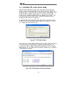
Page 54: ...icrosoft Internet Explorer is configured as the default FTP application An authentication dialog will appear refer to Figure 51 Enter the currently configured user name and case sensitive password defaults are root and icc respectively then click Log On Figure 51 FTP Authentication The web browser will then display the filesystem s contents refer to Figure 52 FTP access via a web browser allows vi...

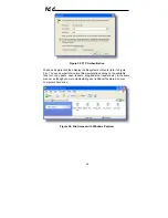
Page 55: ...firewalls and service packs In the Address field type in ftp root and then the IP address of the target interface card if the user name has been changed from its default then replace root in ftp root with the new user name Refer to Figure 54 Figure 54 FTP Navigation with Windows Explorer You will then be presented with an authentication dialog refer to Figure 55 The user name will already be fille...

Page 56: ...fer to Figure 56 You can now perform normal file manipulation actions on the available files cut copy paste open rename drag and drop transfers etc in the same manner as though you were manipulating any traditional file stored on your computer s hard drive Figure 56 File Access with Windows Explorer ...

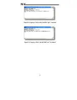
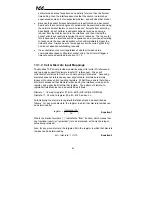
Page 57: ...ient will connect to the unit and then prompt for the username and case sensitive password defaults are root and icc respectively Upon successful entry of the authentication information you will be presented with an ftp prompt Refer to Figure 57 Figure 57 FTP Initiation and Authentication At this point you can use standard Unix style file and directory manipulation commands to perform such actions...

Page 58: ...57 ICC Figure 59 Copying a File from the Unit With get Command Figure 60 Copying a File to the Unit With put Command ...

Page 59: ...ve password default is icc The Port Timeout and Retries fields should already contain the default values Click the Connect button when done Core FTP LE will then try to connect and authenticate to the FTP server and if successful will populate the right hand side of the main page with the unit s filesystem contents Refer to Figure 62 Files can be easily downloaded from the unit by choosing the app...

Page 60: ...nt applications Core FTP LE has a wide array of configuration and file management capabilities which are beyond the scope of this manual Refer to the program s Help file for more detailed instructions Figure 62 Core FTP in Connected State ...

Page 61: ... protocol in the same manner as uploading a configuration XML file Some notes on uploading new firmware via FTP are Please be sure to read the firmware release notes and updated user s manual for any important notices behavior precautions or configuration requirements prior to updating your firmware For example upgrading to a new firmware version may affect user defined configuration files prior t...

Page 62: ...15 Force multiple coils 2 16 Write multiple registers 0 Drive registers can be addressed as either holding registers 4X references or input registers 3X references For example accessing the output frequency involves accessing holding register 41301 or input register 31301 i e offset 1301 Specific bits within drive registers can be accessed as either coils 0X references or discrete inputs 1X refere...

Page 63: ... in section 10 7 4 13 1 2 Coil Discrete Input Mappings The Modbus TCP driver provides read write support for coils 0X references and read only support for discrete inputs 1X references These will collectively be referred to from here on out as simply discretes Accessing discretes does not reference any new physical data discretes are simply indexes into various bits of existing registers What this...

Page 64: ...r function For clarity let s use Equation 1 and Equation 2 in a calculation example Say for instance that we are going to read coil 34 Using Equation 1 we can determine that coil 34 resides in register 3 as 3 0625 3 r1 3 Then using Equation 2 we can determine that the bit within register 3 that coil 34 targets is 34 1 16 1 as 33 16 mod 2 r1 1 Therefore reading coil 34 will return the value of regi...

Page 65: ...processing time of the node during run time I O messages are short and have low overhead which allows for the time critical performance needed by controllers The interface card supports both explicit and I O messaging Further two different types of I O messaging are supported One type invoked when the client opens a connection to the interface using assembly instances 20 70 or 21 71 is included wi...

Page 66: ...he interface card supports the ODVA AC DC drive profile No special Ethernet IP configuration of the interface card is required when using the AC DC drive profile all that is needed is that the controller must target either assembly instances 20 70 or 21 71 in its connection parameters The AC DC drive profile implementation provides support for several required CIP objects which are specified in Ta...

Page 67: ...rection 1 and bit 10 run stop 1 Note that if both the Run Fwd and Run Rev bits are on then inverter register 1007 will not be changed from its previous value Fault Reset Inverter reset command 0 no action 0 1 rising edge reset Maps to inverter register 1007 bit 13 fault reset NetCtrl Run stop control source selection 0 local control 1 network control Maps to inverter register 1007 bit 15 command p...

Page 68: ... will be 1 whenever inverter register 1302 bit 9 direction is 1 and bit 10 running stopped is 1 and will be 0 otherwise Ready Inverter ready signal 0 not ready 1 ready The Ready bit will be 1 whenever the Drive State attribute see below is in the Ready Enabled or Stopping state CtrlFromNet Inverter command reference status 0 command reference is not from network 1 command reference is from network...

Page 69: ...This section will demonstrate how to initially setup a ControlLogix PLC such as a 1756 L61 coupled with a 1756 ENBT communications bridge adjust this procedure according to your specific equipment Later sections will provide specific read write examples using this configuration with I O or explicit messaging 1 Run RSLogix 5000 and create a new configuration 2 To add a 1756 ENET B to your I O confi...

Page 70: ...ode Right click on the 1756 ENET B module in the I O Configuration and choose Properties 10 Select the Port Configuration tab from the Module Properties dialog box 11 Confirm that the IP Address Subnet Mask and Gateway Address fields are configured correctly The IP Address must match the IP Address entered when the new module was first created Refer to Figure 65 Figure 65 Confirming the Module s P...

Page 71: ...cally synchronized at an interval defined by the Requested Packet Interval RPI 1 Switch to offline mode 2 Right click on the 1756 ENET B node under the I O Configuration in the controller organizer view and choose New Module 3 Choose Generic Ethernet Module in the Select Module dialog box and click OK Refer to Figure 66 Figure 66 Adding a New Generic Ethernet Module 4 The module properties dialog ...

Page 72: ...therefore set the Input Size to 2 Output The Output Assembly is the collection of command configuration data that is sent as an output from the PLC and consumed by the interface card Its structure is defined by the Consumed Register Configuration as described in section 10 8 4 The Output Assembly Instance must be set to 100 when connecting to the vendor specific I O assembly instances or 20 21 whe...

Page 73: ... card is 10ms Click OK when done Figure 68 Module Properties Connection Tab 6 After adding the I O Module to the configuration the full I O Configuration tree should appear similar to Figure 69 7 Switch to online mode and download the project to the PLC Verify that the newly added drive is available and operating correctly by observing any indications shown on the drive s icon When the drive s ico...

Page 74: ...rd Command 1 register A value of 0xC400 therefore means that the frequency priority command priority and run bits have been turned ON Similarly we can see that the second 16 bit word of output data ASD_G9ETH O Data 1 has been set to a decimal value of 1234 Once again referring back to Figure 37 we can see that the second element of the consumed register configuration references register 1008 which...

Page 75: ...r 1008 wr_reg_1008 Read inverter status 1 register 1402 rd_reg_1402 Additionally a few special tags exist which provide backward compatibility with V1 000 network interface CPU firmware These are specified in Table 4 Table 4 Special Tag Reference Service Tag Name Register Start Same As Data table read rd_reg_basic 1 rd_reg_1 Data table read rd_freq_out 1401 rd_reg_1401 Data table read rd_inv_stat1...

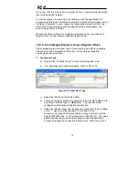
Page 76: ...of registers from the drive with a single MSG instruction Only one read request is outstanding at any given time 1 Create new Tags a Double click Controller Tags in the controller organizer view b The Controller Tags window appears Refer to Figure 72 Figure 72 Create New Tags c Select the Edit Tags tab at the bottom d Create a new tag by entering connection in the first blank Name field and change...

Page 77: ...tination tag size is large enough to hold all elements to be read 2 Add a MSG instruction to the main program a Double click MainRoutine under Tasks MainTask MainProgram in the controller organizer view b Right click on the first ladder logic rung in the MainRoutine window and select Add Ladder Element c The Add Ladder Element window appears d Select the MSG instruction in the Input Output folder ...

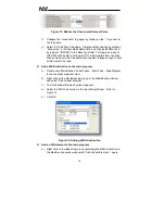
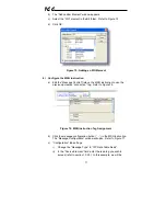
Page 78: ...uction to use the previously created connection tag Refer to Figure 76 Figure 76 MSG Instruction Tag Assignment b Click the message configuration button in the MSG instruction The Message Configuration window will open Refer to Figure 77 c Configuration tab settings i Change the Message Type to CIP Data Table Read ii In the Source Element field enter the read tag you wish to access refer to sectio...

Page 79: ... directly rd_reg_11 to achieve the same results Figure 77 MSG Instruction Configuration iii Enter the Number Of Elements to read In this example we will read 25 registers iv For the Destination Element either directly type in data_array 10 or select element 10 in the data_array tag via the drop down box refer to Figure 78 The destination could be any offset in the data_array tag as long as the off...

Page 80: ...ocal_ENB 2 target_IP_address where Local_ENB is the name of the 1756 ENBx module in the local chassis we named ours EIP in section 13 2 3 2 is the Ethernet port of the 1756 ENBx module in the local chassis and target_IP_address is the IP address of the target node In our example this path would be entered as EIP 2 192 168 16 128 Figure 79 Setting the Communication Path ...

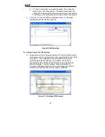
Page 81: ...ssign a tag to the XIO element a Double click on the XIO element located to the left of the MSG block In the drop down box double click on the connection EN field Refer to Figure 81 This configuration causes the MSG instruction to automatically retrigger itself when it completes While this is acceptable for the purposes of this example it can produce high network utilization In actual practice it ...

Page 82: ...re 82 Complete Program 7 Save download and run the program a To view the values of the registers being read from the interface card double click Controller Tags in the controller organizer view Figure 83 Viewing the Register Values b Select the Monitor Tags tab ...

Page 83: ...r and place it in the first element offset 0 of data_array Figure 84 Read the Drive s Status Register 13 2 8 ControlLogix Example Multiple MSG Instructions At times reading from different groups of registers may be necessary For example a specific application may require some registers located in various disjoint locations in the register map To accomplish this task efficiently multiple MSG instru...

Page 84: ...erformed monitoring data is typically written to the remote device only when necessary i e when the value to write has changed This conserves both network bandwidth and potentially EEPROM lifespans on the target device The en_wr element in this example therefore would typically be replaced in an actual application program by user provided logic which controls the conditions under which a write ope...

Page 85: ...84 ICC Figure 86 Reading and Writing via MSG Instructions Figure 87 MSG Configuration for Writing ...

Page 86: ...n Equation 3 target register 1 1485 file number 10 24 which means N10 N24 and offset is restricted only by the limitations of the programming software but is a value of 1485 max Table 5 provides some examples of various combinations of file section numbers and offsets elements which can be used to access drive registers Note that there are multiple different combinations of file section numbers an...

Page 87: ...s configured with a Data Table Address from which to start the access and a Size in Elements which determines the number of items to access read or write The Data Table Address is constructed by selecting a File Section Number and an Offset Element according to Equation 3 For example a File Section Number of N23 and Offset Element of 5 N23 5 which corresponds to register 1305 the drive s input vol...

Page 88: ... file This file will be used to store the incoming data read from the interface card Enter a file number e g 18 set the type to Integer enter a descriptive name e g DATA and enter a number of elements e g 200 Refer to Figure 89 Click OK to create the file Figure 89 Creating a Data File ...

Page 89: ...d select Insert Rung c Right click on the rung number of the new editable rung and select Append Instruction d Select the MSG instruction from the Input Output classification then click OK Refer to Figure 90 Figure 90 MSG Instruction Selection 4 Add an XIO element to the program a Right click on the rung number of the rung currently being edited and select Append Instruction again b Select the XIO...

Page 90: ...d to PLC5 Local Remote field to Local and Control Block to N20 0 b Upon hitting the ENTER key while in the Control Block entry box the MSG Properties dialog box should appear or it can be opened by clicking on the Setup Screen button at the bottom of the MSG instruction Refer to Figure 92 Figure 92 MSG Configuration General Tab ...

Page 91: ...ster 11 and set the MultiHop field to Yes to cause the MultiHop tab to appear e Under the MultiHop tab settings set the To Address in the first row to the drive s IP address and the To Address in the second row to 0 Refer to Figure 93 Figure 93 MSG Configuration MultiHop Tab f Close the dialog box At this point the program should appear as shown in Figure 94 Figure 94 PLC Program after MSG Instruc...

Page 92: ...fer to Figure 95 Figure 95 Completed PLC Program 8 Save download and run the program a To view the registers being read from the interface card double click the data file N18 under Data Files in the controller organizer view 25 register values starting at register 11 are being continuously read from the interface card and placed in the 25 sequential offsets of N18 starting at N18 11 Refer to Figur...

Page 93: ...e necessary For example a specific application may require some registers located in various disjoint locations in the register map To accomplish this task efficiently multiple MSG instructions can be implemented in the PLC program The configuration and execution for implementing multiple MSG instructions is in general identical to that required for implementing just one MSG instruction Each MSG i...

Page 94: ... 99 shows an example of two MSG instructions one for reading and one for writing Note that the Read Write field of each of the MSG instructions is set according to their function Figure 100 shows the configuration details of the write MSG instruction Note that this instruction will only be writing to one drive register namely the frequency command Target Data Table Address is N20 8 which equates t...

Page 95: ...94 ICC Figure 99 Reading and Writing via MSG Instructions Figure 100 MSG Configuration for Writing ...

Page 96: ...er featuring reduced high frequency noise reduced harmonics and high precision and high speed torque control with or without sensors BACnet Standard Device Profile Annex L BACnet Operator Workstation B OWS BACnet Building Controller B BC BACnet Advanced Application Controller B AAC BACnet Application Specific Controller B ASC BACnet Smart Sensor B SS BACnet Smart Actuator B SA BACnet Interoperabil...

Page 97: ...use 11 medium ______ Other ______ Device Address Binding Is static device binding supported This is currently for two way communication with MS TP slaves and certain other devise Yes No Networking Options Router Clause 6 List all routing configurations Annex H BACnet Tunneling Router over IP BACnet IP Broadcast Management Device BBMD Does the BBMD support registrations by Foreign Devices Yes No Ch...

Page 98: ...orted object type Service Object Type Read Property Write Property Analog Output Real Real Unsigned Integer Null Analog Input Real N A Binary Output Enumerated Enumerated Boolean Real Unsigned Integer Null Binary Input Enumerated N A Notes The Null data type is used to relinquish a previously commanded entry at the targeted priority in the priority array When writing to Binary Output objects all n...

Page 99: ...l Software Revision R Protocol Version R Protocol Revision R Services Supported R Object Types Supported R Object List R Max APDU Length R Segmentation Support R APDU Timeout R Number APDU Retries R Max Master Max Info Frames Device Address Binding R Database Revision R Present Value R W R W Status Flags R R R R Event State R R R R Reliability R R R R Out of Service R R R R Units R R Priority Arra...

Page 100: ...STATUS ST programmable input terminal status on off BI6 RES_PIT_STATUS RES programmable input terminal status on off BI7 S1_PIT_STATUS S1 programmable input terminal status on off BI8 S2_PIT_STATUS S2 programmable input terminal status on off BI9 S3_PIT_STATUS S3 programmable input terminal status on off BI10 S4_PIT_STATUS FS4 programmable input terminal status on off BI11 OUT1_POT_STATUS OUT1 pro...

Page 101: ...on off BO9 DATA_OUT2_TERMINAL Output terminal selected data out 2 on off BO10 DATA_OUT3_TERMINAL Output terminal selected data out 3 on off Analog Input Object Instance Summary Instance ID Object Name Description Units AI1 OUTPUT_FREQ Output frequency Hz AI2 LOAD_CURRENT Output current Percent AI3 OUTPUT_VOLTAGE Output voltage Percent AI4 INPUT_POWER_CONSUME Input power KW AI5 RR_ANALOG_INPUT RR S...

Page 102: ...atus of the S2 programmable input terminal ASD parameter FE06 bit 5 BI9 Indicates the status of the S3 programmable input terminal ASD parameter FE06 bit 6 BI10 Indicates the status of the S4 programmable input terminal ASD parameter FE06 bit 7 BI11 Indicates the status of the OUT1 programmable output terminal ASD parameter FE07 bit 0 BI12 Indicates the status of the OUT2 programmable output termi...

Page 103: ...ing to the command source hierarchy and the use of overrides ASD parameter FA06 bit 5 BO8 Output terminal data out 1 Any programmable output terminals that are configured to output specified data output 1 will follow the value of this BO ASD parameter FA50 bit 0 BO9 Output terminal data out 2 Any programmable output terminals that are configured to output specified data output 2 will follow the va...

Page 104: ...his value as its active frequency command if the Frequency Mode parameter is set to Communication Option Input Enabled or if the frequency override bit BO6 is ON Although the adjustment range for this object is 0 40000 0 00Hz 400 00Hz the actual frequency command will be internally limited by the Upper Limit Frequency and Lower Limit Frequency parameters ASD parameter FA07 AO2 Adjusts the FM analo...

Page 105: ... total of 84 modules are available for selection by the controller Refer to the GSDML file for specific module information No explicit module selection is required on the interface card the module will be selected automatically according to the controller s configuration The Profinet IO driver does not trigger timeout events section 10 7 4 ...

Page 106: ...Suite 212 Middleton WI USA 53562 4720 Cypress TX USA 77429 8364 Tel 608 831 1255 Fax 608 831 2045 http www iccdesigns com Printed in U S A ASD INTERFACE SERIES ICC INDUSTRIAL CONTROL COMMUNICATIONS INC ASD G9ETH MULTIPROTOCOL ETHERNET INTERFACE FOR TOSHIBA G9 VFAS1 ADJUSTABLE SPEED DRIVES August 2008 ICC 10639 2 100 000 ...

Reviews: