background image

22

GN-1010 User’s Manual — Using the Utility Software

Configuration

The utility software allows you to set the GN-1010.  This section explains the basic
operation flow for configuration.
For the detailed information on setting parameters, see the section  "Functions of the
Utility Software" (P.24).

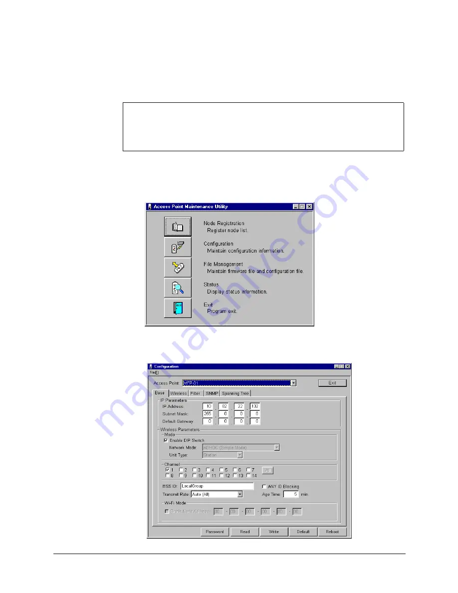
1.

Launch the utility software.

2.

Click [Configuration] from the main menu.

3.

Click the Access Point drop-down list and select the 

access point you want to set or edit.

Parameters in the configuration dialog box displayed when you click [Configuration] in 
step 2 are those for the utility software default setting.  Therefore, you must register 
an appropriate name for this device to the "Name" field as described in the preceding 
section "Node Registration" and click [Read] to load the current setting before per-
forming the setting operation.

Summary of Contents for GN-1010

Page 1: ...MULTIFUNCTIONAL DIGITAL COLOR SYSTEMS Operator s Manual for Wireless LAN Adapter GN 1010 ...

Page 2: ... complies with the IEEE 802 11 standard on wireless LANs Revision B Caution Take the following precautions when handling this product Do not attempt to modify this device The manufacturer will bear no responsibility whatsoever for the device if it has been modified Do not store this device in high temperature or low temperature surroundings or expose it to rapid tem perature changes Operating temp...

Page 3: ...rds and recommendations TOSHIBA believes Wireless LAN is safe for use by consumers These standards and recommendations reflect the consensus of the scientific community and result from deliberations of panels and committees of sci entists who continually review and interpret the extensive research literature In some situations or environments the use of Wireless LAN may be restricted by the propri...

Page 4: ...with products not related to our company we do not take any responsibility Usage Restrictions Do not use the Wireless Products for controlling equipment Equipment directly linked with human life corresponds to the following Medical equipment such as life support systems equipment used in operation etc Exhaust systems for gases such as poisonous gas etc and exhaust systems for smoke Equipment that ...

Page 5: ...oor fire alarm or other automatic control equipment Radio waves can potentially affect automatic control equipment thereby causing an accident due to malfunction Monitor possible radio interference or other troubles to other equipment while the prod uct is used If any effect is caused do not use the product Otherwise radio waves can potentially affect other equipment thereby causing an acci dent d...

Page 6: ... 300 826 General EMC requirements for radio equipment Hereby TOSHIBA TEC declares that this FX DS110 APL GN 1010 is in compli ance with the essential requirements and other relevant provisions of Directive 1999 5 EC TOSHIBA TEC vakuuttaa täten että FX DS110 APL GN 1010 tyyppinen laite on direktiivin 1999 5 EY oleellisten vaatimusten ja sitä koskevien direktiivin muiden ehtojen mukainen Hierbij ver...

Page 7: ...n Übereinstimmung mit den grundlegenden Anforderungen und den anderen relevanten Vorschriften der Richtlinie 1999 5 EG befindet BMWi Hiermit erklärt TOSHIBA TEC die Übereinstimmung des Gerätes FX DS110 APL GN 1010 mit den grundlegenden Anforderungen und den anderen relevanten Fes tlegungen der Richtlinie 1999 5 EG Wien ΜΕ ΤΗΝ ΠΑΡΟΥΣΑ TOSHIBA TEC ΗΛΩΝΕΙ ΟΤΙ FX DS110 APL GN 1010 ΣΥΜΜΟΡΦΩΝΕΤΑΙ ΠΡΟΣ Τ...

Page 8: ...t are believed to be accurate however if any discrep ancies noted should be brought to the attention of TOSHIBA authorized dealer or service engineer Notwithstanding the foregoing the manufacturer is unable to accept any claims for losses or lost profits etc Resulting from the use of this product TOSHIBA TEC will not guarantee the machine performance if you perform any set ting other than specifie...

Page 9: ... 2 pcs Used to secure the GN 1010 on the Multifunc tional Digital System Used to secure the rec ommended hub on the Multifunctional Digital System Used to secure the AC adapter bracket Earth Cable Securing Screw 1 pc Used to secure the earth cable on the GN 1010 CD ROM 1 pc Contains the utility software and the pdf ver sion of this manual Installation Manual 1 pc Explains the unpacking and install...

Page 10: ...eaning it can be connected by LAN cable to any Ethernet compatible Multifunctional Digital System for immediate wireless LAN use This manual explains how to use the GN 1010 Be sure to read it carefully so you can use the product correctly Features It can be installed on the Multifunctional Digital System for space saving Operates as an access point or a LAN station Uses compact lightweight AC adap...

Page 11: ... Europe EU Declaration of Conformity 5 USA Federal Communications Commission FCC 6 PRECAUTIONS RELATED TO SERVICE 7 NOTES 7 BEFORE USING PRODUCT 8 Product Configuration 8 Configuration List 8 INTRODUCTION 9 Features 9 TABLE OF CONTENTS 10 OVERVIEW 12 Component Locations 12 LED Indicators 13 DIP Switches 14 Multi channel Operations 15 OPERATING MODE 16 Infrastructure Wi Fi Mode 16 Station ST 16 Acc...

Page 12: ...8 Bridge 49 Spanning Tree 50 Wireless Counter 51 TROUBLESHOOTING 52 When Communications Fails 52 Check Software 52 Check Peripheral Environment or Installation Location 52 When Device Cannot Be Detected Automatically By Node Registration 53 When Device Does Not Start 53 Check Power LED 53 APPENDIX 54 Product Specifications 54 External Dimensions 54 Physical Specifications 54 Software Specification...

Page 13: ...s The DIP switches are used for initialization and operating mode selection Power Supply Switch Always select power supply from the AC adapter DC side UTP Connector The UTP connector is used to connect the LAN cable Caution Do not obstruct the ventilation slots This can cause heat buildup which can lead to damage or failure LED Power Supply Switch DIP Switches Ground Terminal Power Supply Plug UTP...

Page 14: ...Description POWER Flashing Startup or startup error Illuminates Operating Flashing 2 times Initializing error Flashing 3 times Firmware writing error WLINK Illuminates Wireless LAN is connected normally WRX Flashing Receiving wireless LAN data LINK Illuminates Wired LAN is connected normally RX Flashing Receiving wired LAN data POWER WLINK WRX All flashing simul taneously Firmware writing in progr...

Page 15: ...hen set the same ESS ID as that of the access point When the WEP function is used the WEP key setting is also required No ON OFF Description 1 INIT Used to initialize the GN 1010 1 Turn the power of the GN 1010 ON 2 LED indicators POWER WLNK WRX begin to flash 3 While they are flashing approx 3 seconds turn the DIP switch 1 OFF Before restarting or turning the power off wait until the LED indicato...

Page 16: ...ly affect communications by interference with each other s transmissions Refer to the figure below when selecting channels to ensure the frequency bands do not overlap The maximum number of channels which can be used simultaneously without inter ference is three By using a combination of channels 1 6 11 Channel numbers can be set from 1 to 11 using utility software Channel numbers can be set from ...

Page 17: ...e Station ST When connecting to another access point the GN 1010 can communicate with as a station The GN 1010 can be connected to the network via the access point Access Point AP The GN 1010 operates as an access point and can receive communication from another wireless terminal ...

Page 18: ...eparately Use a straight cable which connects between the hub and the GN 1010 The straight cable is not included with this product The recommended hub can be directly attached to the Multifunctional Digital Sys tem For details contact your TOSHIBA authorized dealer or service engineer In the infrastructure Wi Fi mode all the wireless terminals perform communica tions via the access point Since the...

Page 19: ...between the GN 1010 and PC To set the GN 1010 using the utility software one Windows PC is required Ensure that the DIP switch 2 is OFF Connection with Cross Cable Connection with Hub DIP Switch 1 2 3 4 OFF OFF OFF ON DIP Switch 1 2 3 4 OFF OFF OFF ON Attached Cross Cable Straight Cable Hub ...

Page 20: ...D ROM in the CD ROM drive of the com puter 2 Use Windows Explorer to copy the file APUTIL EXE in the Utility holder from the CD ROM to the appro priate directory Example C WLANUTIL 3 Double click the APUTIL EXE file to open the Access Point Maintenance Utility 4 You will see the following main menu ...

Page 21: ... Registration each time you start the utility 1 Launch the utility software 2 Click Node Registration from the main menu 3 Click Search to detect an access point MAC address and IP address for each access point detected are dis played in the Access Point List 4 From the list double click an access point of which the name is registered When an access point cannot be detected close the utility softw...

Page 22: ...sing the Utility Software 21 5 Enter the access point name and click OK Up to 32 characters are allowed Also a maximum of 1024 devices can be registered 6 Click Exit to complete the detection Program returns to the main menu ...

Page 23: ...y software 2 Click Configuration from the main menu 3 Click the Access Point drop down list and select the access point you want to set or edit Parameters in the configuration dialog box displayed when you click Configuration in step 2 are those for the utility software default setting Therefore you must register an appropriate name for this device to the Name field as described in the preceding s...

Page 24: ... enter it and click OK 6 Click the appropriate tab and edit the parameters For detailed information of the configuration menu refer to the section Configuration P 26 7 After the setting is completed click Write 8 Click Reboot to restart the GN 1010 After restarting the GN 1010 the setting becomes effective Click Read to check whether the setting becomes effective ...

Page 25: ...ected in the Access Point drop down list This funciton can read and write the configuration information of the selected device Also it can save the current configuration informa tion as a text format file and load the saved file File Management Manages configuration file and firmware This function can update the firmware version for the selected device Also it can read and write the configuration ...

Page 26: ...024 devices can be registered To modify the data displayed in the Access Point List double click the access point you want to modify to open the edit window You can also use the File Management menu to save the current Access Point List data on the hard disk or load a previously saved file Button Description Search This function automatically detects and registers all devices con nected to the sam...

Page 27: ...ssword effective the reboot opera tion is required 4 Read Reads the configuration for the selected device 5 Write Writes the currently displayed configuration to the selected device To make the configuration effective the reboot operation is required 6 Default Restores the factory default setting To apply the setting write the configuration to the device and reboot it 7 Reboot Reboots the selected...

Page 28: ...trator Default Gateway 2 0 0 0 0 Enters the IP address of the default gateway Wireless Parame ters Enable DIP Switch Disabled Determines whether or not the DIP switch is used Enabled Disabled Network Mode Infrastruc ture Wi Fi Mode Selects the wireless operating mode ADHOC Simple Mode Infrastructure Standard Mode Infrastructure Wi Fi Mode Infrastructure Advanced Mode The GN 1010 supports Infrastru...

Page 29: ...ice belongs Up to 32 alphanumerics case sensitive Communication between the wireless devices with different names is not possible Network can be split by changing the name ANY ID Blocking Disabled Determines whether or not the log in from a station which has no ESS ID is refused Enabled Disabled When Enable is set the log in from a device which has no ESS ID will be refused Transmit Rate Auto All ...

Page 30: ...yption Hexadecimal value 0 to 9 A to F To perform communications using the WEP function the key placed in the default send key number used for trans mission must be the same as that placed in the same location on the receiver Key 2 to 4 Disabled Exten sion Control Extended Roaming 1 Disabled Sets the AP roaming method Enabled Disabled When enabled AP Login Priority setting is allowed Roaming Thres...

Page 31: ... value which is applied when the extension speed is changed from 5 5 Mbps to 2 Mbps or vice versa in Extension Speed Control When Extension Speed Control is enabled the setting is allowed Border of 2M and 1M Setting is not allowed 70 Sets the RSSI value as the threshold value which is applied when the extension speed is changed from 2 Mbps to 1 Mbps or vice versa in Extension Speed Control When Ex...

Page 32: ...AP2 to login When ST transfers from 3 to 4 the connection of AP2 and RSSI 80 cannot be used Therefore log out is performed from AP2 however in this case the wire less connection is disconnected because of lack of AP which is allowed to login Roaming is performed after the transfer the following occurs if there are two or more APs which are allowed to login When AP Login Priority is not specified l...

Page 33: ...n using the GN 1010 as a station you can use this function There is a station logged in to AP at 1 with the transmission speed 11Mbps RSSI value is retained at 90 or more When the station transfers to 2 RSSI 90 or below and RSSI 80 or more Extension Speed Control function will be activated and the transmission speed will be changed to 5 5Mbps When it transfers to 3 or 4 the speed will be changed t...

Page 34: ...ss is refused MAC Address List 1 Displays the permitted MAC address list when MAC Address Filter is enabled You can register or delete MAC address one by one by New or Delete command You can also load the batch list from the list file and save a list as the list file Up to 1024 addresses can be registered Protocol Filter Enable Pro tocol Filter Disabled Determines whether or not the protocol filte...

Page 35: ...n This can refuse log in to APs to unknown user units which have not registered When MAC addresses of UU1 and UU2 are registered in the MAC address filter list and the address of UU3 is not UU1 and UU2 can login to AP however UU3 cannot login To permit UU3 to login to AP the AP administrator must add MAC address of UU3 to the MAC address filter list MAC Filter List UU1 UU2 AP UU1 UU2 UU3 ...

Page 36: ...ss Specified by range NodeAddress Start MAC Address End MAC Address Specified individually NodeAddress MAC Address Example of LOGFLIST AP Login Filter Tables First Line Not omissible APLoginFilter Enabled Not omissible Enabled Disabled NodeAddress 00 80 4C 00 00 00 00 80 4C FF FF FF T Company Specified by range NodeAddress 00 80 11 00 00 03 A Person Specified individually NodeAddress 00 80 21 00 0...

Page 37: ...fic of a protocol which is not usually used and reduce unnec essary use of the wireless bands When protocol A is registered in the protocol filter list owned by AP and other proto cols such as B are not packet of protocol A can pass bridge through AP however packet of protocol B is discarded when passing through AP Protocol Filter List Protocol A AP Protocol B and others Protocol A UU Discard ...

Page 38: ... ProtocolType Ethernet Type IP Protocol Start Pot Number End Port Number Specified individually ProtocolType Ethernet Type IP Protocol Port Number Special Format ProtocolType IP Permits all the IP protocols ProtocolType IP TCP Permits all the TCP Port 0 to 65535 ProtocolType IP UDP Permits all the UDP Port 0 to 65535 Example of PRTFLIST Protocol Filter Table First Line Not omissible ProtocolFilter...

Page 39: ...e Utility Software Registering the MAC Address Filter 1 Check Enable MAC Address Filter box 2 Click New 3 Enter address to Wireless MAC Address 1 4 When specified by range check Range box and enter address to Wireless MAC Address 2 5 Click OK ...

Page 40: ...GN 1010 User s Manual Functions of the Utility Software 39 6 Registered information is displayed on the MAC Address List ...

Page 41: ...Functions of the Utility Software Registering the Protocol Filter 1 Check Enable Protocol Filter box 2 Click New 3 Select Ethernet from Ethernet Type drop down list 4 Set IP Protocol and IP Port Protocol as required 5 Click OK ...

Page 42: ...GN 1010 User s Manual Functions of the Utility Software 41 6 Registered information is displayed on the Protocol List ...

Page 43: ...42 GN 1010 User s Manual Functions of the Utility Software SNMP This function is excluded from support Spanning Tree This function is excluded from support ...

Page 44: ... Selects file name or directory name 3 Get Version Obtains the version information This obtains the verison information from all the devices connctected to the same network group or from only the designated device To obtain data from a device which exists beyond the IP router always select the device first In this case the IP parameter must be set correctly 4 Read 1 Reads the firmware and setting ...

Page 45: ...sh interval to read information 0 to 120 sec 3 Information Tab Status information items are organized into each tab 4 Exit Returns to the main menu 5 Scan Start Periodically reads and diplays information the refresh interval is specified in Interval When Interval is 0 information is read only once 6 Stop Stops reading information Scan Stop 7 Clear Clears the displayed information You can operate t...

Page 46: ...irmware Version Wireless Card Version number of wireless card firmware Hardware Version Version number of hardware Ethernet Address Ethernet address assigned to this device Wireless MAC Address Wireless MAC address assigned to this device IP Address Current IP address of this device Subnet Mask Current subnet mask Default Gateway Current default gateway IP address Network Mode Current operating mo...

Page 47: ...tate Interface operating state State Description up Operating down Not operating or not linked Receive Octets Number of bytes received Receive Packets Number of packets received Receive Discards Number of packets discarded due to insufficient memory Receive Errors Number of packets with receive errors Receive Errors CRC Number of packets received with CRC error If this error occurs frequently on t...

Page 48: ...ons of the Utility Software 47 Transmit Waits Number of packets waiting to be transmitted Transmit Errors Number of packets with transmit errors Resets Number of times for which this interface has been reset Parameter Description ...

Page 49: ... AP Quality 1 Link quality between this device and logged in AP Noise Level 1 Noise level on station side Wireless Node List Unit type station Information of logged in AP Unit type AP Infromation of wireless device Wireless MAC Address MAC address of wireless device State Login state applicable when infrastructure mode is set Age Time Time to retain device information sec It is retained while the ...

Page 50: ...iption MAC Address MAC addresses of devices connected to the network Interface Displays the device is on either Ethernet side or wireless side Ethernet Wireless Age Time Time for which this device information is retained minute Retained while this device is communicating When the time reaches 0 it will be deleted Wireless MAC Address MAC addresses of logged in wireless devices Displayed when devic...

Page 51: ...50 GN 1010 User s Manual Functions of the Utility Software Spanning Tree Information of this tab is excluded from support ...

Page 52: ...nsmitted by another station using multi cast adderss TX Deferred Transmissions Number of packets for which the transmission is delayed TX Single Retry Frames Number of packets retransmitted only once TX Multiple Retry Frames Number of packets retransmitted multiple times TX Discards Number of packets discarded RX Unicast Frames Number of packets received by another station using unicast adderss RX...

Page 53: ... channel setting has been correctly entered Check if the communication speed setting has been correctly entered Check Peripheral Environment or Installation Location A nearby source of electromagnetic interference can prevent communication In general locations excluding factories the following may be sources of electro magnetic emissions 2 4GHz band wireless networks not compatible with IEEE 802 1...

Page 54: ...tes the utility software is the DHCP client exit the soft ware When approx 1 minute has passed open the software again When Device Does Not Start Check Power LED Check that the power LED is on When extinguished Check if the AC adapter is correctly plugged into the power supply con nector and an outlet Check if the power supply switch is in DC side Check whether or not the power LED is flashing Whe...

Page 55: ...ransmission For mat IEEE 1802 11b standard DS spectrum diffusion Data Transmission Speed 11 5 5 2 1Mbps fixed automatic Access Method CSMA CA ACK RTS CTS Transmission Packet IEEE 802 11b frame Wireless Category Low power data transmission system 2400 to 2472MHz Aerial Power 10mW MHz or below Security WEP Operating Mode Infrastructure access point settings available External Dimensions mm 81 W x 26...

Page 56: ...RFC 826 SNMP RFC 1157 MIB II RFC 1213 Item Description Supply Voltage 5 5 to 7 0 VDC using AC adapter Consumption Current 0 6A Max Operating Temperature 0 to 50 C main unit 0 to 40 C AC adapter Operating Humidity 10 to 90 without condensation Airborne dust Not extreme Corrosive Gas None Other Do not obstruct ventilation slits Leave 5 cm open space in all directions Pin No Signal 1 TD 2 TD 3 RD 4 U...

Page 57: ...mes cannot be performed Wireless network can be partitioned by using different ESS ID names IEEE Institute of Electrical Electronics Engineers I triple E involved in a wide range of fields from communications and computer to medicine and biology with primary activities related to publishing articles and sponsor ing conferences but also recommending and setting of standards The organization sponsor...

Page 58: ...other Bridge A device for relaying between LAN s The bridge determines whether to relay data based on the address of the computer to which the data is being sent It can be used to connect networks having different protocols or when data for broadcast to all comput ers is received can send this to all connected networks Router A device for relaying between LAN s The router determines data addresses...

Page 59: ......

Page 60: ......

Page 61: ......

Page 62: ...HIBA TEC CORPORATION All rights reserved 1 1 KANDA NISHIKI CHO CHIYODA KU TOKYO 101 8442 JAPAN R03072038200 TTEC 2003 09 MULTIFUNCTIONAL DIGITAL COLOR SYSTEMS Operator s Manual for Wireless LAN Adapter GN 1010 ...

Reviews: