Guide Specification – 3-Phase Static Uninterruptible Power Supply
9
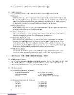
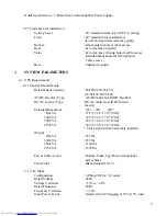
Harmonic Voltage Distortion
: < 2% THD (100% Linear Load)
: < 5% THD (100% Non-linear Load)
Phase Displacement
: 1° Maximum at 100% load
Voltage Transients:
100% Load Step Change
: +/-2% Maximum (Without battery assistance)
Loss or Return of Input
: +/-1% Maximum
Transfer from Bypass to Inverter : +/-5% Maximum
(At Bypass Rated Voltage)
Recovery Time
: 1 cycle
5
FUNCTIONAL DESCRIPTION
The UPS shall protect the load against surges, sags, undervoltage, and voltage fluctuation. The
UPS shall have built-in protection against permanent damage to itself and the connected load for
all predictable types of malfunctions. The load shall be automatically transferred to the bypass
line without interruption in the event of an internal UPS malfunction. The status of protective
devices shall be indicated on a LCD graphic display screen on the front of the UPS.
5.1
IGBT Rectifier
5.1.1 General
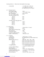
A solid-state, multi-level IGBT Rectifier shall convert the incoming AC power into DC
power to supply the inverter input and system battery.
5.1.2 Voltage Regulation
The rectifier output voltage shall not deviate by more than +/- 1.0% RMS under the
following conditions:
0% - 100% loading (balanced and unbalanced loading, non-transient)
+15% - 20% utility voltage change
+/-10.0% utility frequency change
5.1.3 Reflected Harmonic Content
Input current THD shall be
< 3% at 60%-100% load
< 6% at 25%-59% load.
5.2
IGBT DC-DC Converter
5.2.1 General
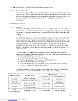
A solid-state IGBT Battery Converter/Charger shall control battery charging.
5.2.2 Battery Charge Current Limit
The Converter logic shall provide DC for controlled battery charging. The battery current
sensing shall be independent of the Converter DC Output current sensing to provide
precise battery recharging control. The DC/DC Charging Converter shall include a circuit
to regulate the battery charging current to between 100% and 125%.


