Toshiba G9000 SERIES Specifications Download Page 10

Guide Specification – 3-Phase Static Uninterruptible Power Supply 
 

10 

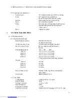
5.2.3   Battery Protection 

The converter shall be provided with monitoring and control circuits to protect the battery 
system from damage due to excessive discharge. Converter shutdown shall be initiated 
when the battery voltage reaches a discharge cutoff voltage of 400 VDC.  Automatic 
shutdown based on discharge time is not acceptable. 

 
5.2.4  DC Ripple 

AC Ripple on the DC Bus shall be less than 0.2%. 
AC Ripple on the Battery charging circuit shall be less than 0.23% for the 80/100/160 
kVA UPS, and less than 0.29% for the 225 kVA UPS.  


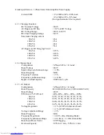
5.3


IGBT Inverter:  
 
5.3.1  General 

The inverter shall be composed of multi-level IGBT power transistors controlled utilizing 
an Advanced Technology PWM logic.  The Inverter shall continuously convert DC power 
from the IGBT Rectifier to AC power for the critical loads. When the utility voltage or 
frequency exceeds the specified UPS input tolerances, the inverter shall continuously 
convert DC power from the battery source to AC power for the critical load.  


The inverter shall be capable of providing rated output while operating at any battery 
voltage within the battery operating range. When the DC battery voltage reaches the 
operational low voltage limit during a loss of utility AC power, the inverter shall 
automatically shut off. 

 
5.3.2   Output Voltage  

The Inverter output voltage shall not deviate by more than +/- 1.0% RMS under the 
following steady state conditions as the Inverter DC input varies from maximum to 
minimum: 


0% to 100%Unbalanced load 


0% to 100%Balanced load 

 
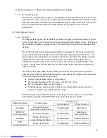
5.3.3   Synchronization  

The Inverter output voltage shall be automatically synchronized with the bypass AC 
source as long as the source is within the tolerable frequency and voltage range. If the 
bypass AC source is not within the range, the control circuitry will stop synchronization 
and operate the inverter in free running mode. When the bypass AC source recovers to 
within tolerance, the inverter shall change its frequency (slew rate 1Hz/sec) and track the 
bypass AC source until synchronization is achieved without causing any disturbance to 
the load.  

 
5.3.4  Output Control 

The Inverter can be manually started and stopped using the LCD touch screen controls. 


Summary of Contents for G9000 SERIES

Page 1: ...RATE OFFICE 13131 WEST LITTLE YORK ROAD HOUSTON TX 77041 PHONE 713 466 0277 800 231 1412 FACSIMILE 713 896 5226 1 TOSHIBA G9000 80 100 160 225 kVA GUIDE SPECIFICATION THREE PHASE UNINTERRUPTIBLE POWER SUPPLY ...

Page 2: ...Guide Specification 3 Phase Static Uninterruptible Power Supply 2 ...

Page 3: ...rameters 6 3 2 2 Discharge Heat from UPS 6 3 2 3 Clearances for installation 7 4 SYSTEM PARAMETERS 7 4 1 UPS REQUIREMENTS 7 4 1 1 General Requirements 7 5 FUNCTIONAL DESCRIPTION 9 5 1 IGBT RECTIFIER 9 5 2 IGBT DC DC CONVERTER 9 5 3 IGBT INVERTER 10 5 4 STATIC BYPASS CIRCUIT 11 5 5 METERING MONITORING ALARMS AND CONTROLS 12 6 MECHANICAL DESIGN 14 6 1 UPS ENCLOSURE 14 6 2 CABLE ACCESS 14 7 WARRANTY ...

Page 4: ...IBA DISTRIBUTION CABNET TDC OPTION 16 11 MAINTENANCE BYPASS PANEL OPTION 16 11 1 SITE INSTALLATION 16 11 2 ELECTRICAL CONFIGURATION 16 11 3 MECHANICAL INTERLOCK 16 11 4 EXTERNAL MAINTENANCE BYPASS 16 12 AUXILIARY TRANSFORMER CABINETS OPTION 16 13 POWER DISTRIBUTION UNITS OPTION 16 14 EXTENDED SERVICES OPTION 17 ...

Page 5: ...ds The UPS shall be designed in accordance with and be compliant with the following sections of the current revisions of the following standards UL 1778 cUL Listed FCC Class A Article 47 Part 15 B ISO 9001 ISO 14001 ANSI C62 41 2 2 Components The UPS shall consist of the following components 1 Multi level IGBT AC DC Rectifier 2 IGBT DC DC Battery Converter Charger 3 Multi level IGBT DC AC Inverter...

Page 6: ... UPS controls shall automatically transfer the critical load from the inverter output to the bypass AC source without interruption When the overload or internal warning condition is removed after a preset hold period the UPS will automatically re transfer the critical load from the bypass to the inverter output without interruption of power to the critical load 2 3 5Maintenance Bypass An optional ...

Page 7: ...60 225 kVA 72 90 144 202 5 kW AC DC Rectifier Type AC DC multi level IGBT Rectifier DC AC Inverter Type DC AC multi level IGBT Inverter Inverter External Dimensions W D H 80 kVA 27 6 x 32 8 x 78 7 80 6 100 kVA 27 6 x 32 8 x 78 7 80 6 160 kVA 35 4 x 32 8 x 78 7 80 6 225 kVA 35 4 x 32 8 x 78 7 80 6 Unit height with fan assembly installed Weight 80 kVA 855 lbs 100 kVA 855 lbs 160 kVA 1160 lbs 225 kVA...

Page 8: ... voltage synchronous range 10 Rated frequency 60 Hz Frequency Variation 5 Frequency synchronous range 1 0 Hz Bypass overload capacity 1000 for 1 cycle 4 1 5 AC Output Configuration 3 Phase 3 Wire Ground Rated Capacity 80 100 160 225 kVA 72 90 144 202 5 kW Rated Voltage 480 V Efficiency at Full Load 20 40 60 80 100 80 kVA 92 5 95 6 95 6 95 6 95 6 100 kVA 92 5 95 6 95 6 95 6 95 6 150 kVA 94 6 96 2 9...

Page 9: ...raphic display screen on the front of the UPS 5 1 IGBT Rectifier 5 1 1 General A solid state multi level IGBT Rectifier shall convert the incoming AC power into DC power to supply the inverter input and system battery 5 1 2 Voltage Regulation The rectifier output voltage shall not deviate by more than 1 0 RMS under the following conditions 0 100 loading balanced and unbalanced loading non transien...

Page 10: ...ource to AC power for the critical load The inverter shall be capable of providing rated output while operating at any battery voltage within the battery operating range When the DC battery voltage reaches the operational low voltage limit during a loss of utility AC power the inverter shall automatically shut off 5 3 2 Output Voltage The Inverter output voltage shall not deviate by more than 1 0 ...

Page 11: ... the thyristor switch be energized and upon closure maintain the bypass source to the load to improve the efficiency and reliability of the system The thyristor switch shall only be utilized for the time needed to energize the contactor closure The UPS system logic shall employ sensing which shall cause the thyristor switch to energize and provide an uninterrupted transfer of the load to the bypas...

Page 12: ...ill automatically switch the power flow from the bypass circuit to the main circuit inverter without interruption 5 5 Metering Monitoring Alarms and Controls 5 5 1 Status Indicators The Front Panel shall include LED status indicators for the following states Load on Inverter Battery Operation Load on Bypass Overload LCD Fault UPS Fault 5 5 2 EPO Emergency Power Off Button The Front Panel shall hav...

Page 13: ...solated Control Signals Normally Open isolated contact signal outputs for remote use will be furnished for the following operating status indications Summary Alarm Load on Bypass Load on Inverter Battery Operation Rectifier Operation Battery Low Voltage Overload Total alarm Output Contactor Closed Contact rating Output 1 A 30 VDC Input 24 VDC UPS module accepts remote switches to initiate the foll...

Page 14: ...even years pro rata Parts labor and travel are included during warranty period Optional extended warranties shall be available See Toshiba warranties at www toshiba com ind 7 3 Warranty Support Availability Warranty and technical support shall be available 24 7 365 877 867 8773 8 BATTERY CABINETS OPTION The UPS manufacturer can provide optional matching battery cabinets with DC breaker 9 COMMUNICA...

Page 15: ...ervers Network Adapter External Hardware AMD 188ES 20MHz 512kB SRAM 512kB Flash Two asynchronous serial ports 10 BaseT RJ 45 connector Toshiba UPS communication protocol SNMP over UDP IP HTTP over TCP IP ARP RARP TFTP and ICMP MIB_II Toshiba v1 2_MIB JEM MIB RFC 1628 Traffic LED for network Status LED for status Power LED for Power 2 digit default setting is Switches 1 and 2 off Temperature Range ...

Page 16: ...nce Bypass A manually operated maintenance bypass panel can be provided to bypass the power feeding the critical load from inverter to a static switch panel without causing any power interruption Bypass input breaker can supply input power to the UPS module static bypass input If the system design calls for separate UPS and bypass inputs a bypass input breaker can be installed on each input UPS ma...

Page 17: ...r can offer Startup Service Maintenance Contracts Silver Gold Platinum Preventive Maintenance Contracts Spare parts kits A B and C level Extended warranty coverage for up to an additional 5 years Enhanced warranty contract 24 7 Holiday coverage Load bank testing Factory witness testing Site monitor and power audits ...

Reviews: