background image

1 - 11

© 2003 - 2008 TOSHIBA TEC CORPORATION All rights reserved

1

e-STUDIO350/352/353/450/452/453

SPECIFICATIONS

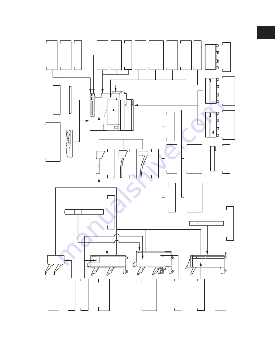
1.5.2  e-STUDIO352/353/452/453

Work Tray

KK-3511

Antenna

GN-3010

Memory

GC-1230

Printer/

Scanner Kit

. ELK

GM-2060/2061

GM-2120

Scanner Kit

. ELK

GM-4060

GM-4120

Printer Kit

. ELK

GM-1060/1061

GM-1120

Wireless LAN

Module

GN-1041

e-BRIDGE

ID Gate

KP-2005

e-BRIDGE

ID Gate

KP-2004

Bluetooth

Module

GN-2010

Data

Overwrite Kit

GP-1060

Platen Cover

KA-3511

Reversing Automatic

Document Feeder

( RADF

)

MR-3018

Bridge Kit

KN-3520

Job Separator

MJ-5004

Offset Tray

MJ-5005

Scrambler

Board

GP-1040

PCI Slot

GO-1060

FAX Board

GD-1200

NA/EU/AU/AS/

C/TW/KR

2nd Line for

FAX Board

GD-1160

NA/EU-N/TW/C

Damp Heater

MF-3520 U/E

Desk

MH-1700

Drawer Module

MY-1021

Large Capacity

Feeder (LCF)

KD-1012 A4/LT

Paper Feed

Pedestal (PFP)

KD-1011

Hole Punch Unit

MJ-6101 N/E/F/S

Staple Cartridge

STAPLE-1600

Staple Cartridge

STAPLE-2000

Hole Punch Unit

MJ-6004 N/E/F/S

Staple Cartridge

STAPLE-600

Staple Cartridge

STAPLE-2400

Finisher

( Hanging type

)

MJ-1022

Finisher

( Console type

)

MJ-1023

Finisher

( Console type

)

MJ-1101

Finisher

( Console saddle

stitcher type)

MJ-1024

Fig. 1-502

08/04

Summary of Contents for e-Studio 350

Page 1: ...SERVICE MANUAL MULTIFUNCTIONAL DIGITAL SYSTEMS e STUDIO350 450 e STUDIO352 452 e STUDIO353 453 Model DP 3520 3540 4520 4540 Publish Date November 2003 File No SME030028I0 R03092140702 TTEC Ver09_2008 04 ...

Page 2: ... tries Apple AppleTalk Macintosh and Mac are trademarks of Apple Computer Inc in the U S and other countries PostScript is a trademark of Adobe Systems Incorporated NOVELL NetWare and NDS are trademarks or registered trademarks of Novell Inc Molykote is a registered trademark of Dow Corning Corporation iCLASS is a trademark of HID Corporation MIFARE is a trademark of Royal Philips Electronics Othe...

Page 3: ...operation keep a minimum clearance of 80 cm 32 on the left 80 cm 32 on the right and 10 cm 4 in the rear The socket outlet shall be installed near the equipment and shall be easily accessible Be sure to fix and plug in the power cable securely after the installation so that no one trips over it 2 Service of Machines Basically be sure to turn the main switch off and unplug the power cord during ser...

Page 4: ...ed by Toshiba TEC Corporation 4 Cautionary Labels During servicing be sure to check the rating plate and the cautionary labels such as Unplug the power cord during service Hot area Laser warning label etc to see if there is any dirt on their surface and whether they are properly stuck to the equipment 5 Disposition of Consumable Parts Packing Materials Used batteries and RAM ICs Regarding the reco...

Page 5: ...ion 2 22 2 4 1 System block diagram 2 22 2 4 2 Construction of boards 2 24 2 5 Installation and Replacement of Covers and PC boards 2 26 2 5 1 External covers 2 26 2 5 2 PC boards 2 32 2 6 Options 2 40 3 COPY PROCESS 3 1 3 1 General Description of Copying Process 3 1 3 2 Details of Copying Process 3 2 3 3 Comparison with DP4500 3500 3 10 4 GENERAL OPERATION 4 1 4 1 Overview of Operation 4 1 4 2 De...

Page 6: ...n 6 4 6 3 1 Scan motor 6 4 6 3 2 Scanning drive circuit 6 5 6 3 3 Initialization at power ON 6 7 6 4 Control of Exposure Lamp 6 8 6 4 1 General description 6 8 6 4 2 Exposure lamp 6 9 6 4 3 Control circuit for the exposure lamp 6 10 6 5 General Description of CCD Control 6 11 6 5 1 Opto electronic conversion 6 11 6 5 2 Shading correction 6 11 6 6 Automatic Original Size Detection Circuit 6 12 6 6 ...

Page 7: ...ray up Motor 9 9 9 4 Disassembly and Replacement 9 10 10 DRIVE SYSTEM 10 1 10 1 General Description 10 1 10 2 Functions 10 1 10 3 Main Motor 10 2 10 3 1 Main motor drive 10 2 10 3 2 Control signals 10 3 10 4 Disassembly and Replacement 10 4 11 DRUM RELATED SECTION 11 1 11 1 Configuration 11 1 11 2 Functions 11 2 11 3 Output Control Circuits of High Voltage Transformer 11 5 11 3 1 Overview 11 5 11 ...

Page 8: ...r 13 5 13 4 3 IH control circuit interface 13 6 13 4 4 Relation between system configuration and IH output 13 7 13 4 5 Temperature detection section 13 8 13 4 6 Abnormality in the IH control circuit 13 13 13 5 Control Circuit of Exit Motor 13 15 13 6 Exit Motor Drive 13 15 13 7 Disassembly and Replacement 13 16 14 AUTOMATIC DUPLEXING UNIT ADU 14 1 14 1 General Description 14 1 14 2 Description of ...

Page 9: ...rophotographic process dry Type Desktop type console type when paper feed pedestal PFP and large ca pacity feeder LCF are installed Original table Fixed type the left rear corner used as guide to place originals Accepted originals Sheet book and 3 dimensional object The reversing automatic document feeder RADF only accepts paper which are not pasted or stapled Carbon paper are not acceptable eithe...

Page 10: ...Reproduction ratio Actual ratio 100 0 5 Zooming 25 to 400 in increments of 1 25 to 200 when using RADF Resolution Gradation Scanning 600 dpi x 600 dpi Printing Equivalent to 2400 dpi x 600 dpi Gradation 256 steps The system copy speed including scanning time is available when 10 sheets of A4 LT size original are set on RADF and one of the copy modes in the left table is selected The period of time...

Page 11: ...ht 11 mm equivalent to 100 sheets 64 to 80 g m2 17 to 22 lb Capacity of originals in the reversing automatic document feeder Option A3 to A5 R LD to ST R 100 sheets 80 g m2 Stack height 16 mm or less Automatic duplexing unit Stackless Switchback type Toner supply Automatic toner density detection supply Toner cartridge replacing method Density control Automatic density mode and manual density mode...

Page 12: ...e STUDIO350 352 353 450 452 453 SPECIFICATIONS Dimensions of the equipment See the figure below W660 x D718 x H739 mm e STUDIO350 450 W660 x D758 x H739 mm e STUDIO352 353 452 453 When the tilt angle of the control panel is 45 degrees Fig 1 101 45 W D H 07 11 ...

Page 13: ...5 11 Unpacking setup instruction 1 set Operator s manual 4 pcs except for MJD Operator s manual pocket 1 pc Power cable 1 pc Warranty sheet 1 pc for NAD Setup report 1 set for NAD and MJD Customer satisfaction card 1 pc for MJD PM sticker 1 pc for MJD Drum installed inside of the equipment 1 pc Toner bag 1 pc Toner cartridge 1 pc except for NAD MJD Developer material 1 pc except for NAD MJD Operat...

Page 14: ...F MR 3015 Drawer Module MY 1021 C Paper Feed Pedestal PFP KD 1011 C Large Capacity Feeder LCF KD 1012 A4 LT A4 C Finisher Hanging type MJ 1022 C Finisher Console type MJ 1023 C Finisher Console saddle stitcher type MJ 1024 C Hole Punch Unit MJ 6004 N E F S 1 Staple Cartridge STAPLE 1600 for MJ 1022 STAPLE 2000 for MJ 1023 1024 STAPLE 600 for MJ 1024 Bridge Kit KN 3520 C Job Separator MJ 5004 C Off...

Page 15: ... 6004N E F S Staple cartridge STAPLE 1600 for MJ 1022 STAPLE 2400 for MJ 1101 STAPLE 2000 for MJ 1023 1024 STAPLE 600 for saddle stitcher of MJ 1024 Bridge kit KN 3520 C Job separator MJ 5004 C Offset tray MJ 5005 C Work tray KK 3511 C Damp heater MF 3520U E Fax board GD 1200NA EU AU AS C TW KR 2nd line for fax board GD 1160NA EU N C TW Printer kit GM 1060 1061 Printer Scanner kit GM 2060 2061 Sca...

Page 16: ... scrambler board GP 1040 4 The antenna GN 3010 is necessary to enable the wireless LAN module GN 1041 and Bluetooth module GN 2010 5 When the wireless LAN module GN 1041 and the Bluetooth module GN 2010 are in stalled only 1 antenna GN 3010 can be connected to each 6 The Printer kit GM 1060 or Printer Scanner kit GM 2060 does not have a function for printing an XPS file 7 To enable an XPS file to ...

Page 17: ...453 SPECIFICATIONS 1 4 Supplies 2 N Asia E Europe NONE North America 3 T Taiwan D Asia C China E Europe NONE North America Drum OD 3500 Toner bag PS TB3520 E N 2 Toner cartridge PS ZT3520 T D C E 3 e STUDIO350 352 450 452 PS ZT3520 C 3 PS ZT4520 E 3 e STUDIO353 453 Developer D 3500 07 11 ...

Page 18: ... Board GP 1030 PCI Slot GO 1030 FAX Board GD 1150 NA AU EU TW C AS 2nd Line for FAX Board GD 1160 NA EU TW C Wireless LAN Adapter GN 1010 Damp Heater MF 3520 U E Printer Kit GM 1010 Desk MH 1700 Drawer Module MY 1021 Large Capacity Feeder LCF KD 1012 A4 LT Paper Feed Pedestal PFP KD 1011 Printer Scanner Kit GM 2010 Data overwrite kit GP 1050 Scanner Upgrade Kit GM 3010 Staple Cartridge STAPLE 2000...

Page 19: ...Document Feeder RADF MR 3018 Bridge Kit KN 3520 Job Separator MJ 5004 Offset Tray MJ 5005 Scrambler Board GP 1040 PCI Slot GO 1060 FAX Board GD 1200 NA EU AU AS C TW KR 2nd Line for FAX Board GD 1160 NA EU N TW C Damp Heater MF 3520 U E Desk MH 1700 Drawer Module MY 1021 Large Capacity Feeder LCF KD 1012 A4 LT Paper Feed Pedestal PFP KD 1011 Hole Punch Unit MJ 6101 N E F S Staple Cartridge STAPLE ...

Page 20: ...1 12 2003 2008 TOSHIBA TEC CORPORATION All rights reserved 1 e STUDIO350 352 353 450 452 453 SPECIFICATIONS ...

Page 21: ...3 2008 TOSHIBA TEC CORPORATION All rights reserved 2 OUTLINE OF THE MACHINE 2 1 Sectional View Fig 2 101 2 3 4 5 7 0 2 3 4 5 7 20 2 22 23 23 24 25 2 27 2 2 30 3 32 33 34 35 3 37 3 3 40 4 42 43 44 45 4 47 4 4 50 5 52 53 54 55 5 5 57 5 0 2 3 4 5 7 70 7 72 3 4 5 20 2 ...

Page 22: ...tection sensor 2 17 Drawer 53 Auto toner sensor 18 Drawer tray 54 Toner recovery auger 19 Drawer tray up sensor 55 Developer sleeve magnetic roller 20 Drawer empty sensor 56 Fuser roller 21 Drawer paper stock sensor 57 Pressure roller 22 Drawer damp heater JPD only 58 Cleaning roller 23 Registration roller 59 IH coil 24 Registration sensor 60 Main thermistor Edge thermistor 25 Upper drawer feed se...

Page 23: ...2 e STUDIO350 352 353 450 452 453 OUTLINE OF THE MACHINE 2 2003 2008 TOSHIBA TEC CORPORATION All rights reserved Fig 2 102 3 2 5 4 7 5 4 7 2 3 2 0 20 2 23 22 25 24 2 27 2 ...

Page 24: ...ght 19 Bypass pickup solenoid 6 Scanner damp heater thermostat 20 Bypass feed clutch 7 IH board cooling fan 21 Side cover opening closing switch 8 Developer unit cooling fan 1 22 Transport clutch High speed 9 Toner motor 23 Transport clutch Low speed 10 Developer drive clutch 24 Lower drawer feed clutch 11 Main motor 25 Tray up motor 12 Exit motor 26 Drawer detection switch 13 Toner bag full detec...

Page 25: ...OSHIBA TEC CORPORATION All rights reserved 2 2 Electric Parts Layout A Unit construction Fuser unit Front side Laser unit PC board unit Fig 2 201 Scanner unit Drive unit Control panel unit Automatic duplexing unit Bypass unit Process unit Paper feeder unit Transport unit ...

Page 26: ...53 OUTLINE OF THE MACHINE 2003 2008 TOSHIBA TEC CORPORATION All rights reserved B Scanner unit B 1 Motor sensor lamp LT series Fig 2 202 2 A4 series Fig 2 202 1 Front side M1 S7 S6 EXP S3 S2 S1 S5 S4 Front side M1 S7 S6 EXP S3 S2 S5 S4 ...

Page 27: ...NE 2003 2008 TOSHIBA TEC CORPORATION All rights reserved B 2 PC board heater thermostat other part C Control panel unit Front side Fig 2 204 LCD KEY DSP Fig 2 203 ASD AUD CND SAD TWD models Standard NAD MJD models Option Front side INV THMO2 DH1 DH2 CCD SLG ...

Page 28: ...TION All rights reserved D Process unit D 1 Motor sensor switch PC board D 2 Motor sensor lamp heater thermistor thermostat Fig 2 206 ASD AUD CND SAD TWD models Standard NAD MJD models Option Fig 2 205 Front side ERS THM3 PS THMO3 M16 S11 DH3 Front side S9 LRL M8 S8 S32 S30 S31 S12 M9 S10 ...

Page 29: ... 353 450 452 453 OUTLINE OF THE MACHINE 2003 2008 TOSHIBA TEC CORPORATION All rights reserved E Laser unit Fig 2 207 Front side SNS LDR M2 F Paper feeder unit Fig 2 208 Front side CLT2 CLT1 S20 S22 S21 S23 S16 S18 S17 S19 ...

Page 30: ...50 352 353 450 452 453 OUTLINE OF THE MACHINE 2003 2008 TOSHIBA TEC CORPORATION All rights reserved H Bypass unit G Transport unit Fig 2 209 Front side M10 S13 S14 S33 S15 M11 Front side Fig 2 210 SFB CLT3 SOL1 S25 S24 ...

Page 31: ... 450 452 453 OUTLINE OF THE MACHINE 2003 2008 TOSHIBA TEC CORPORATION All rights reserved J Fuser unit Fig 2 212 Front side I Automatic duplexing unit S26 S27 Fig 2 211 ADU M3 CLT4 S28 Front side IH COIL THM1 THM2 M12 THMO1 S29 ...

Page 32: ...2 12 2 e STUDIO350 352 353 450 452 453 OUTLINE OF THE MACHINE 2003 2008 TOSHIBA TEC CORPORATION All rights reserved K Drive unit Front side Fig 2 213 M6 CLT8 HVT M7 CLT7 CLT6 CLT5 M14 M5 M4 IH M13 M15 ...

Page 33: ... OF THE MACHINE 2003 2008 TOSHIBA TEC CORPORATION All rights reserved L PC board unit e STUDIO350 450 Fig 2 214 NAD SAD TWD models FIL Standard ASD AUD CND models FUS Standard MJD model FUS Option Front side SYS LGC BRK NF NIC HDD FIL or FUS 05 11 ...

Page 34: ... OUTLINE OF THE MACHINE 2003 2008 TOSHIBA TEC CORPORATION All rights reserved 07 11 e STUDIO352 353 452 453 Fig 2 215 LGC HDD M17 SYS NF BRK FUS Front side NAD SAD TWD models FIL Standard ASD AUD CND models FUS Standard MJD model FUS Option ...

Page 35: ... trays in upper lower drawer K P4 I26 M7 TNR MOT Toner motor Supplying the toner K P28 I9 M8 LSU FAN MOT Laser unit cooling fan Cooling down the laser unit D 1 P9 I3 M9 MID FAN MOT Middle fan Cooling down the inside of the equipment D 1 P9 I3 M10 EXIT FAN MOT Exhaust fan Exhausting ozone G P11 I2 M11 SP FAN MOT Sub separation fan Assisting the paper separation process Absorbing the paper from the ...

Page 36: ... I19 S12 TEMP HUMI SNR Temperature humidity sensor Detecting the temperature and humidity inside of the equipment D 1 P5 I15 S13 RGST SNR Registration sensor Detecting the paper transport at the registration roller section G P19 I11 S14 FED U SNR Upper drawer feed sensor Detecting paper jam and paper transport at upper drawer feeding section G P19 I11 S15 FED L SNR Lower drawer feed sensor Detecti...

Page 37: ...exing unit opening closing detection I P32 I43 S27 ADU TRU SNR ADU entrance sensor Detecting the transporting paper at automatic duplexing unit entrance section I P32 I31 S28 ADU TRL SNR ADU exit sensor Detecting the transporting paper in automatic duplexing unit I P32 I31 S29 EXIT SNR Exit sensor Detecting the transporting paper at the exit section J P31 I21 S30 MAIN SW Main switch Turning ON OFF...

Page 38: ...h Driving the bypass pickup roller and bypass feed roller H P17 I20 CLT4 ADU CLT ADU clutch Driving the automatic duplexing unit I P32 I16 CLT5 RGST CLT Registration clutch Driving the registration roller K P19 I31 CLT6 DEV CLK Developer drive clutch Driving the magnetic roller of the developer unit K P12 I36 CLT7 CST TR L CLT Transport clutch Low speed Driving the transport roller Low speed K P15...

Page 39: ... the laser diode E P9 I5 SNS PWA F SNS H sync signal detection PC board SNS board Detection of the laser beam position E P9 I5 SFB PWA F SFB Bypass tray slide guide width detection PC board SFB board Detection of the bypass tray slide guide width H P16 I13 ADU PWA F ADU ADU driving PC board ADU board Controlling the automatic duplexing unit I P32 I30 IH PS IH IH control PC board IH board Controlli...

Page 40: ...ASD AUD CND SAD TWD models Standard NAD MJD models Option B 2 P10 I32 DH3 DRM DH Drum damp heater Preventing condensation of the drum ASD AUD CND SAD TWD models Standard NAD MJD models Option D 2 P27 I7 Symbol Name Function Remarks P I THM1 THMS C HTR Main thermistor Detecting the surface temperature at the center part of the fuser roller J P29 I10 THM2 THMS S HTR Edge thermistor Detecting the sur...

Page 41: ...ansfer bias Separation bias K P4 I29 Symbol Name Function Remarks P I INV INV EXP Inverter board Controlling the exposure lamp B 2 P21 I7 LCD LCD LCD panel Displaying and entering each information C P3 I19 PS PS ACC Switching power supply Generating DC voltage and supplying it to each section of the equipment D 2 P9 I7 HDD HDD Hard disk Storing the program data and image data L P7 I25 P7 I103 NF N...

Page 42: ...4MB x 2 Download jig Download jig Download jig IPC PFP LCF RADF ADU Motors HVT Clutches Sensors Solenoids Switches Bypass unit Key copy counter Copy key card Finisher Bridge unit Job separator Offset tray Bus transceiver Bus transceiver I O Finisher Control panel PCI external slot USB connector host 1 USB connector device USB connector host 2 RS 232C Parallel port IEEE 1284 HDD NCU LINE 1 NCU LINE...

Page 43: ... key card Finisher Bridge unit Job separator Offset tray Bus transceiver I O Finisher CCD Flash ROM 512KB SRAM 128KB Amp Amp A D A D Odd Even ASIC ASIC Engine CPU 24MHz ASIC ASIC Motors Scanner CPU 22MHz Laser diode FRAM 256KB Control panel ASIC Page memory SDRAM 16MB x 2 PSTN External TEL PSTN SRAM 512KB Battery RTC EEPROM 1KB Flash ROM 8MB x 2 Download jig PCI slot Scrambler board USB connector ...

Page 44: ...nd outputs it to the SLG board SLG board This is the board to mainly control the scanning function scanner unit and consists of the Scanner CPU ASIC memory Flash ROM and SRAM A D converter driver for motor drive etc When scanning the original the exposure lamp and scan motor are driven by the command from the Scanner CPU The analog signal output from the CCD board is then converted to digital sign...

Page 45: ... This is the board to generate the electric power for driving the IH coil of the fuser unit from the AC electric power input via the switching power supply And then it is provided SYS board This is the main board taking a leading part in all systems It consists of the System CPU ASIC memory DIMM SDRAM Flash ROM SRAM NVRAM RTC Real Time Clock IC etc The System CPU controls each ASIC to perform the ...

Page 46: ... power to the damp heater for condensation prevention of each section scanner and drum FUS board This is the board to provide the AC electric power for driving to the damp heater for preventing of the condensation of each section scanner and drum HVT This is the board to generate the DC high voltage from 24V to provide the bias to the section of the main charger developer transfer and separation P...

Page 47: ...502 Fig 2 504 Fig 2 501 Fig 2 503 Guide 2 5 Installation and Replacement of Covers and PC boards 2 5 1 External covers A Front cover 1 Open the front cover 2 Remove the toner bag 3 Pull up the hinge pin and extract it 4 Take off the front cover B Front left cover 1 Open the front cover 2 Remove 1 screw and front left cover ...

Page 48: ...ws and take off the rear cover C 2 e STUDIO352 353 452 453 1 Remove 1 screw and take off the connector cover 2 Remove 2 screws and take off the rear cover 1 3 Remove 3 screws and take off the rear cover 2 Note If the RADF has been installed disconnect the connector of the RADF before the above step Fig 2 506 Fig 2 507 Fig 2 508 07 11 Connector cover Rear cover 1 Rear cover 2 ...

Page 49: ... cover Chapter 2 5 1 D 3 Take off the right upper cover Chapter 2 5 1 F 4 Remove 2 screws and upper rear cover Fig 2 509 Fig 2 510 Fig 2 511 D Left upper cover 1 Remove 2 screws and take off the left upper cover E Front upper cover 1 Take off the left upper cover Chapter 2 5 1 D 2 Remove 2 screws and take off the front up per cover F Right upper cover 1 Remove 3 screws and take off the right up pe...

Page 50: ...eceiving tray 1 Remove 2 screws and take off the receiving tray Fig 2 515 I Tray back cover 1 Take off the receiving tray Chapter 2 5 1 H 2 Take off the scan base cover Fig 2 514 3 Remove 1 screw and take off the receiving tray back cover 1 2 Scan base cover 04 05 Fig 2 516 J Left cover 1 Remove 3 screws and take off the left cover ...

Page 51: ... cover Fig 2 517 Fig 2 518 Fig 2 519 K Left rear cover 1 Take off the left upper cover Chapter 2 5 1 D 2 Remove 3 screws and take off the left rear cover L IH terminal cover 1 Open the ADU jam access cover and fuser unit cover 2 Remove 2 screws and take off the IH termi nal cover M Right front hinge cover 1 Pull out the upper and lower drawers 2 Remove 2 screws and take off the right front hinge c...

Page 52: ... 5 1 N 4 Remove 2 screws and take off the right rear cover Fig 2 521 Fig 2 522 Fig 2 523 O Right lower cover 1 Take off the right rear hinge cover Chapter 2 5 1 N 2 Remove 2 screws and take off the right lower cover Q Front right cover 1 Take off the front cover Chapter 2 5 1 A 2 Take off the receiving tray Chapter 2 5 1 H 3 Take off the right upper cover Chapter 2 5 1 F 4 Take off the upper drawe...

Page 53: ...ds Note When the PC board HDD is replaced refer to each CAUTIONS of TROUBLESHOOTHING in the SERVICE HANDBOOK A Logic PC board LGC board A 1 LGC board 1 Take off the rear cover Chapter 2 5 1 C 2 Loosen 8 screws and take off the LGC board cover 3 Disconnect 14 connectors and 1 connector with lock 4 Remove 4 screws and release 2 locking supports Then take off the LGC board A 2 LGC board unit 1 Take o...

Page 54: ...rs on the case 5 Remove 5 screws and take off the LGC board with the whole case Fig 2 528 Fig 2 529 B Hard disk HDD cooling fan B 1 e STUDIO350 450 1 Take off the rear cover Chapter 2 5 1 C 2 Loosen 9 screws and take off the SYS board upper cover Fig 2 530 Fig 2 531 3 Disconnect 2 connectors 4 Loosen 5 screws and take off the hard disk with the whole SYS board lower cover 05 11 ...

Page 55: ...g 2 532 5 Remove 4 screws and take off the hard disk Fig 2 533 Fig 2 534 Fig 2 535 B 2 e STUDIO352 353 452 453 1 Take off the rear cover 1 chapter 2 5 1 C 2 Disconnect 1 connector Release the har ness from harness clamps 3 Loosen 10 screws and take off the SYS board cover 4 Disconnect 2 connectors 07 11 SYS board cover ...

Page 56: ...nnect 2 connectors and take off the hard disk Remove 1 screw and take off the ground wire 7 Remove 2 screws and take off the HDD cooling fan from the SYS board cover Fig 2 539 C System control PC board case SYS board case C 1 e STUDIO350 450 1 Take off the rear cover Chapter 2 5 1 C 2 Take off the hard disk with the whole SYS board lower cover Chapter 2 5 2 B 3 Disconnect 4 connectors 05 11 Hard d...

Page 57: ...oard case 4 Release all the harnesses from harness clamps and holders on the case Fig 2 540 Fig 2 541 C 2 e STUDIO352 353 452 453 1 Take off the connector cover and rear cover 1 chapter 2 5 1 C 2 Take off the hard disk with the whole brack ets chapter 2 5 2 B 3 Disconnect 4 connectors 4 Release the harnesses from 2 harness clamps Fig 2 542 Fig 2 543 07 11 ...

Page 58: ...46 4 Remove 2 screws release 1 lock support Then take off the NIC board NIC board Fig 2 547 5 Remove 10 screws take off the SYS board SYS board Fig 2 545 D NIC board System control PC board SYS board D 1 e STUDIO350 450 1 Take off the rear cover Chapter 2 5 1 C 2 Take off the hard disk with the whole SYS board lower cover Chapter 2 5 2 B 3 Disconnect 5 connectors 05 11 SYS board case ...

Page 59: ...from the holder on the right side of the bracket Fig 2 551 D 2 e STUDIO352 353 452 453 1 Take off the hard disk with the whole brack ets chapter 2 5 1 B 2 Disconnect 4 connectors Fig 2 548 Fig 2 550 07 11 SYS board 3 Remove 8 screws and take off the SYS board Note Alternatively you can take off the SYS board without removing the hard disk by removing 2 upper and 1 lower fixing screws for the hard ...

Page 60: ...to the color instruction on the board Fig 2 555 H Noise filter 1 Take off the rear cover and right lower cover Chapter 2 5 1 C O 2 Disconnect 4 connectors Remove 1 screw and 1 washer Then take off the noise filter White Black Fig 2 553 F Power supply cooling fan 1 Take off the left cover Chapter 2 5 1 J 2 Remove 2 screws and take off the power supply cooling fan on the switching power supply Note ...

Page 61: ...PORATION All rights reserved Fig 2 601 Fig 2 602 Fig 2 603 Fig 2 604 5 Open the RADF 2 6 Options A MR 3015 Reversing Automatic Document Feeder RADF 1 Turn OFF the power and unplug the power cable 2 Take off the connector cover 3 Disconnect the connector 4 Remove 2 screws on the rear side ...

Page 62: ...nal damp heater 6 Remove 2 screws on the front side 7 Slide the RADF backward and take off by lifting it up B KD 1011 Paper Feed Pedestal PFP 1 Turn OFF the power and unplug the power cable 2 Take off the rear cover of the equipment Chapter 2 5 1 C Note Disconnect the connector of the RADF first when the RADF is installed 3 Remove 1 screw and the ground wire and then disconnect 2 connectors 3 if t...

Page 63: ...awer 6 Remove 4 screws and take off 2 fixing brackets on the front side Fig 2 612 Connector of optional damp heater C KD 1012 Large Capacity Feeder LCF 1 Turn OFF the power and unplug the power cable 2 Take off the rear cover of the equipment Chapter 2 5 1 C Note Disconnect the connectors of the RADF first when the RADF is installed 3 Remove 1 screw and the ground wire and then disconnect 2 connec...

Page 64: ...A TEC CORPORATION All rights reserved Fig 2 615 Fig 2 616 6 Pull out the LCF drawer 7 Remove 4 screws and take off 2 fixing brackets on the front side Fig 2 613 Fig 2 614 5 Take off the lower drawer of the equipment 4 Remove 2 screws and take off 2 fixing brackets on the rear side ...

Page 65: ... LCF is not installed 1 Turn OFF the power and unplug the power cable 2 Take off the connector cover and disconnect the connector Fig 2 617 8 Lift up the equipment and take off the LCF Fig 2 619 3 Remove 2 screws and take off the safety bracket on the rear side and the cover Fig 2 620 4 Remove 2 screws and take off the safety bracket on the front side and the cover ...

Page 66: ...ghts reserved Fig 2 623 Fig 2 624 D 2 When PFP LCF is installed 1 Turn OFF the power and unplug the power cable 2 Take off the connector cover and disconnect the connector 3 Remove 2 screws and take off the cover on the rear side Fig 2 621 5 Remove 2 screws Fig 2 622 6 Lift up the finisher and take it off ...

Page 67: ...ghts reserved Fig 2 626 5 Remove 2 screws Fig 2 625 4 Remove 2 screws and take off the cover on the front side Fig 2 627 6 Lift up the finisher and take it off Fig 2 628 E MJ 1023 Console finisher 1 Turn OFF the power and unplug the power cable 2 Take off the connector cover and disconnect the connector ...

Page 68: ...OSHIBA TEC CORPORATION All rights reserved Fig 2 631 Fig 2 632 5 Remove 1 screw 6 Remove 1 screw and take off the cover of the finisher rear side Fig 2 629 3 Remove 1 screw and take off the finisher lower cover Fig 2 630 4 Remove 3 screws and take off the finisher front cover ...

Page 69: ...ake off the finisher Note Be careful not to fell the finisher when mov ing the finisher unit only Fig 2 633 7 Remove 1 screw Fig 2 635 F MJ 1024 Console finisher 1 Turn OFF the power and unplug the power cable 2 Take off the connector cover and disconnect the connector Fig 2 636 3 Open the finisher front cover and remove 1 screw ...

Page 70: ...40 6 Take off the finisher Note Be careful not to fell the finisher when mov ing the finisher unit only G MJ 6004 Hole punch unit 1 Turn OFF the power and unplug the power cable 2 Take off the connector cover and disconnect connector Fig 2 637 4 Remove 1 screw and take off the cover of the finisher rear side Fig 2 638 5 Remove 1 screw ...

Page 71: ... TOSHIBA TEC CORPORATION All rights reserved Fig 2 642 4 Take off the cover of the punch unit lower side Fig 2 641 3 Open the front cover of the hole punch unit and remove 1 screw Fig 2 643 5 Remove 1 screw Fig 2 644 6 Remove 3 screws and take off the punch unit rear cover ...

Page 72: ...8 TOSHIBA TEC CORPORATION All rights reserved Fig 2 647 Fig 2 648 9 Disconnect 2 connectors 10 Remove 2 screws Fig 2 645 7 Remove 1 screw Fig 2 646 8 Take off the finisher with the hole punch unit Note Be careful not to fell the finisher when mov ing the finisher unit only ...

Page 73: ...All rights reserved Fig 2 650 H KN 3520 Bridge unit 1 Turn OFF the power and unplug the power cable 2 Remove 2 screws and take off the cover Fig 2 649 11 Lift up the punch unit and take it off Fig 2 651 3 Disconnect 1 connector Fig 2 652 4 Open the bridge unit Remove 1 screw and take off the cover ...

Page 74: ...served Fig 2 655 Fig 2 656 7 Lift up the bridge unit and release the hook Take off the bridge unit toward the front I MJ 5004 Job separator 1 Turn OFF the power and unplug the power cable 2 Take off the tray Fig 2 653 5 Close the bridge unit and remove 1 screw Fig 2 654 6 Remove 4 screws and take off the bracket ...

Page 75: ...RPORATION All rights reserved Fig 2 658 4 Disconnect 2 connectors Fig 2 657 3 Remove 2 screws and take off the cover Fig 2 659 5 Loosen 2 screws and take off the cover Fig 2 660 6 Remove 1 screw 7 Lift up the job separator and release the hook Take off the job separator toward the front ...

Page 76: ...SHIBA TEC CORPORATION All rights reserved Fig 2 663 Fig 2 664 4 Disconnect 2 connectors 5 Remove 1 screw and take off the cover Fig 2 662 Fig 2 661 J MJ 5005 Offset tray 1 Turn OFF the power and unplug the power cable 2 Take off the tray 3 Remove 2 screws and take off the cover ...

Page 77: ...1 screw 7 Lift up the offset tray and release the hook Take off the offset tray toward the front K MR 3018 Reversing Automatic Document Feeder RADF 1 Turn the power OFF and unplug the power cable 2 Take off the connector cover Fig 2 666 05 11 Fig 2 667 3 Disconnect the connector Fig 2 668 4 Remove 1 screw and 1 washer on the rear side ...

Page 78: ...HE MACHINE 2003 2008 TOSHIBA TEC CORPORATION All rights reserved Fig 2 671 Fig 2 672 7 Remove 2 screws on the front side 8 Slide the RADF backward and take it off by lifting it up Fig 2 669 Fig 2 670 5 Remove 1 screw on the rear side 6 Open the RADF 05 11 ...

Page 79: ...ake off the connector cover and disconnect 1 connector 3 Open the front cover of the finisher Remove 1 screw and slide the lever to the front side 05 11 Fig 2 675 4 Take off the finisher Note When moving the finisher unit by itself be careful that it does not topple over Fig 2 676 M MJ 6101 Hole punch unit 1 Turn the power off and unplug the power cable 2 Take off the connector cover and disconnec...

Page 80: ...move 1 screw and take off the mainte nance cover 7 Disconnect 1 connector 3 Release the Latches and take off the front lower cover of the hole punch unit Fig 2 677 Fig 2 678 4 Remove 1 screw and slide the lever to the front side 5 Take off the finisher Note When moving the finisher unit by itself be careful that it does not topple over 05 11 ...

Page 81: ...2 61 2 e STUDIO350 352 353 450 452 453 OUTLINE OF THE MACHINE 2003 2008 TOSHIBA TEC CORPORATION All rights reserved 8 Remove 2 screws 9 Take off the hole punch unit Fig 2 681 05 11 ...

Page 82: ...2 62 2 2 e STUDIO350 352 353 450 452 453 OUTLINE OF THE MACHINE 2003 2008 TOSHIBA TEC CORPORATION All rights reserved ...

Page 83: ... onto paper 8 Separation Separates paper with the toner image from the photoconductive drum 9 Fusing Fuses the toner image onto the pa per by applying heat and pressure 10 Cleaning Scrapes off the residual toner from the drum 11 Discharging Eliminates the residual nega tive charge from the surface of the photoconductive drum Original exposure Xenon lamp 16W Data reading scanning CCD 600 dpi 7400 p...

Page 84: ...ial of the areas on the drum corresponding to black areas of the original are eliminated while the areas on the drum corresponding to white areas retains the negative charge As this image on the drum formed by the negative potential is not visible it is called an electrostatic latent image 2 Charging Charging is the process to apply charge evenly on the drum surface The charger wire produces negat...

Page 85: ...mage processing sec tion 4 Data writing Data writing is the process of converting the image signals sent from the image process ing section into optical signal and exposing the drum surface with the light Semiconductive laser element converts image signals transmitted from the image processing section into optical signal laser emission to expose the drum surface and form an electrostatic latent im...

Page 86: ... is lower than the developer bias which is applied to the magnetic roller reverse develop ment method Drum Magnetic roller Fig 3 207 Photoconductive layer Magnet Magnetic roller Toner Carrier always attracted onto the magnet Toner Bias voltage 550 VDC Photoconduc tive drum Aluminum base Toner Fig 3 208 The potential of the photoconductive drum is higher than the devel oper bias The potential of th...

Page 87: ...ote If the developer material is used for a long time beyond its normal life span the toner is caked onto the carrier The charging performance of the carrier is low ered Symptom 1 Image density is lowered 2 Toner scattering occurs 3 Background fogging occurs Solution Replace the developer material Magnetic roller Magnetic brush development The south and north poles are arranged inside the magnetic...

Page 88: ...original background 2 Size and density of originals 3 The existence of solid black when making prints when a book is copied and the original cover is partially opened 4 Temperature and humidity in the room when making prints 5 Prints density and image quality mode As indicated in the figure below the life of the toner cartridge varies depending on the copy mode and coverage of originals 6 A full b...

Page 89: ...harge applied to the paper is normally 286 µA DC However to improve transferability at the trailing edge of the paper lower output 137 µA DC is applied to the part 10 mm from the trailing edge 7 Separation Separation is the process of separating paper which is temporarily adhering to the drum due to the static electricity during the transfer process Method Apply AC voltage to which the nega tive D...

Page 90: ...sin is 100 110 C Heat Toner is melted by the heat of the surface of the fuser roller Pressure The pressure roller is pressed against the fuser roller by the springs to increase the adherence of the melted toner onto the paper Heat and pressure are applied to the paper when it passes between the fuser roller and pressure roller Fusing The toner is fused on the paper Separation finger Drum rotation ...

Page 91: ...e the next charging pro cess If the residual charge is not eliminated the fol lowing phenomenon occurs The negative charge remains on the photo conductive drum Uneven charge is applied to the drum during the next printing The next print will have a double image The preceding image appears Solution The entire surface of the photoconductive drum is illuminated with light by the discharge LED array T...

Page 92: ...artridge Density detection method T 3500 T 3500E T 3500D D 3500 DC 550 V Adjustable output during printing DC 150 V Fixed others T 3520 T 3520E T 3520D T 3520C T 3520T e SDUDIO350 352 452 453 T 4520 T 4520E T 3520C e STUDIO353 453 D 3500 D 3500C 5 Transfer 1 Transfer bias Adjustable output Constant current 580 V Adjustment not required 6 Separation AC Adjustable output Constant voltage DC Adjustme...

Page 93: ...itialization of scanning system The carriage moves to the home position The carriage moves to the peak detection position The exposure lamp is turned ON Peak detection white color is detected by the shading correction plate The exposure lamp is turned OFF READY WARMING UP is displayed 2 Pre running operation The pre running operation is started when the temperature of the fuser roller surface reac...

Page 94: ...g Main charger developer bias and discharge LED ON Fans are rotated in high speed Drawer feed clutch ON The pickup roller feed roller separation roller and transport roller start to rotate Paper reaches the upper drawer feed sensor The upper drawer feed sensor is turned ON Paper reaches the registration roller The registration sensor is turned ON and aligning is performed Drawer feed clutch OFF af...

Page 95: ...reserved 6 Paper exit Exit sensor detects the trailing edge of the paper Main charger developer bias and discharge LED OFF Polygonal motor main motor and exit motor OFF Drum fuser unit and developer unit stop Fans return to the ready rotation READY is displayed and the equipment enters the ready mode ...

Page 96: ...2 22 0 224 20 402 54 45 5 7 4 54 0 4 5 7 0 22 000 500 2000 2500 3000 3500 4000 4500 5000 Timing chart for copying one A4 size sheet fed from the upper drawer Scan motor Exposure lamp Main motor Upper drawer feed clutch Upper drawer feed sensor Registration sensor Registration clutch MVDEN signal Main charger Developer bias Discharge LED Exit sensor ms rev fwd 04 01 ...

Page 97: ...ass feeding Main charger developer bias and discharge LED ON Fans are rotated in high speed Bypass feed clutch ON The bypass pickup roller and bypass feed roller start to rotate The bypass pickup roller is lowered Aligning operation Paper reaches the registration roller After a certain period of time the bypass feed clutch OFF 4 Hereafter the operation 3 through 6 of 4 2 3 Drawer feed copying is r...

Page 98: ...Add paper 2 Paper misfeed in bypass B Abnormality not cleared without turning OFF the door switch 1 Misfeed in equipment 2 Add toner 3 Developer unit not installed properly 4 Toner bag replacement C Abnormality not cleared without turning OFF the main switch 1 Call for service 3 After the interruption copying is finished LED INTERRUPT OFF by pressing the INTERRUPT button Equipment returns to the s...

Page 99: ...rmality A 1 Add paper Drawer empty sensor detects the presence or absence of paper When drawer is not installed No drawer detected Tray not going up drawer empty sensor OFF Add paper displayed START button disabled When drawer is installed Drawer detected Tray going up drawer empty sensor OFF Add paper displayed START button disabled ...

Page 100: ...layed regardless of presence absence of paper Cleared by turning the power ON OFF Tray up sensor is turned ON in a fixed period of time The tray motor stops At this time if the empty sensor is ON It is judged that there is paper OFF It is judged that there is no paper Drawer area of the illustration blinks When the drawer is selected When the paper in the drawer runs out during copying The tray up...

Page 101: ...aper from the bypass tray A 3 Set key copy counter When the key copy counter optional is pulled out from the equipment which installs it Set key copy counter displayed Copying operation disabled When the counter is pulled out during copying Copying is stopped when the key copy counter is pulled out B 1 Misfeed in equipment Exit sensor detects jamming of the leading edge of paper Registration clutc...

Page 102: ...30 Front cover is opened during copying Paper jam E410 Registration sensor detects jamming of the leading edge of paper Registration sensor is not turned ON in a fixed period of time after the leading edge of paper passed the transport roller Paper jam E120 E200 E210 E300 E330 and E3C0 During paper feeding from ADU Registration sensor is not turned ON in a fixed period of time after the ADU clutch...

Page 103: ...d B 3 Developer unit not installed properly Disconnection of the connectors of the developer unit Developer unit not installed is displayed Solution Connect the connectors of the developer unit and close the front cover B 4 Dispose of used toner Toner bag becomes full of toner Toner recovery auger shifts to the rear side Toner bag full detection sensor 1 ON or Toner bag detection sensor 2 ON Dispo...

Page 104: ...S YES NO A B NO NO NO NO NO NO NO NO YES YES YES YES Call for serv ce YES YES YES C2 0 C270 C2 0 Ma n sw tch ON DC power ON Restart Cover s open IH co l ON Paper jam Reg strat on sensor ON Scan motor ON Home pos t on detected Peak detected 2 5 seconds elapsed Call for serv ce Ex t sensor ON ADU entrance ex t sensors ON Upper drawer feed sensor ON Lower drawer feed sensor ON ...

Page 105: ...ON Tray up motor ON Fuser roller reached ready temp Ma n motor OFF READY YES Call for serv ce YES Call for serv ce IH co l broken YES Polygonal motor n abnormal cond t on Call for serv ce NO NO NO NO C4 0 C430 C440 CA 0 YES IH error Call for serv ce NO C470 C4 0 C4 0 Therm stor broken Temperature of the fuser roller ready for pre runn ng ...

Page 106: ...ema n ng set number 0 Process ng system control completed H Sync OK Process ng system control Call for serv ce Polygonal motor normal rotat on CA 0 Transfer charger ON Transfer charger OFF Feed clutch ON Feed clutch OFF Reg strat on clutch ON Counter ON OFF Reg strat on clutch OFF Call for serv ce Laser OFF C Scann ng system control Exposure lamp ON Carr ages move forward Carr ages stopped Exposur...

Page 107: ...15 2003 2008 TOSHIBA TEC CORPORATION All rights reserved OK NG C Polygonal motor OFF Ma n charger OFF D scharge LED OFF Developer b as OFF Ex t motor OFF READY Drum rotat on reversed Ma n motor OFF Paper jam E020 Ex t sensor detected tra l ng edge of paper ...

Page 108: ...4 16 4 e STUDIO350 352 353 450 452 453 GENERAL OPERATION 2003 2008 TOSHIBA TEC CORPORATION All rights reserved ...

Page 109: ... and select various modes and LEDs and an LCD to display the state of the equipment or the messages When the operator s attention is required graphic symbols appear with messages explaining the condition of the equipment in the LCD panel This equipment has a movable control panel which enables to adjust its angle to the operator It also has improved its operatability and visibility with the enlarg...

Page 110: ...5 5 2003 2008 TOSHIBA TEC CORPORATION All rights reserved e STUDIO350 352 353 450 452 453 CONTROL PANEL 5 2 Items Shown on the Display Panel Fig 5 201 Fig 5 202 ...

Page 111: ...tion 9 READY Press START button to copy Copying job interrupted Press START button to resume copying or press MEMORY CLEAR button to delete the job 10 READY WARMING UP Scanner warming up Ready to scan the original 11 READY PRINTING Printing out the data Scanning is enabled 12 READY ADDING TONER Supplying toner Scanning is enabled 13 READY INNER TRAY FULL Receiving tray in the equipment is full Sca...

Page 112: ...conditions are set and START button is pressed with no original placed Cleared by setting the original 30 Change direction of original Displayed when the direction of original placed is different from the setting 31 Place last d originals in doc feeder entrance tray Paper jam occurred during copying RADF scanning 32 Add paper Displayed when the paper in selected drawer is running out 33 Cannot dup...

Page 113: ...heet Insertion Mode 46 Set insert1 sheets in the same direction as the originals Displayed when the direction of insertion sheet sheet 1 is different from that of other pages at Sheet Insertion Mode 47 Set insert2 sheets in the same direction as the originals Displayed when the direction of insertion sheet sheet 2 is different from that of other pages at Sheet Insertion Mode 48 Set transparency fi...

Page 114: ...nough memory to store original s Will you save stored originals in Displayed when confirming the user to save the scanning data as much as stored at memory full state Displayed only in FAX Function 67 The number of originals exceeds the limits Will you copy stored originals Displayed when confirming the user to print out the data as much as stored at memory full state 68 The number of originals ex...

Page 115: ...ording to the messages displayed on the panel 75 Call for service Displayed when motor sensor switch etc do not work properly Turn OFF the power and solve the problem then turn ON the power 76 Please try again after a while Displayed when the Department Code can no be keyed in immediately after power ON Leave it for a while and key in the code again 77 Set standard size Displayed when the paper si...

Page 116: ...ged Display not changed Display not changed Display not changed Printing out the copy Display not changed Displays department code entry screen when department management is available Displays print job list screen Display not changed LED blinking Copy mode is cleared after the copy mode is set Printing out stops and READY Press START to copy and MEMORY CLEAR are displayed Number of printouts chan...

Page 117: ...an STN blue mode transmissive type LCD with 640x240 dot display capacity It con sists of a driver LSI frame printed circuit board and lateral type CCFL backlight STN Super Twisted Nematic CCFL Cold Cathode Fluorescent Lamp 2 Block diagram 40 x 240 IC XSCL UD0 UD UD2 UD3 WF LP VDD GND V0 VEE Power supply LCDEN IC2 LCD PANEL 40 x 240 DOTS IC3 IC4 0 0 0 0 IC5 20 IC 20 Fig 5 401 Fig 5 402 05 11 ...

Page 118: ...from the System control PC board The control methods of the LED and buzzers differ depending on the model e STUDIO350 450 They are switched to ON OFF with the control signals from the System control PC board e STUDIO352 353 452 453 They are switched to ON OFF with the signals output from the panel pro cessing CPU based on serial data transmitted from the System control PC board Fig 5 403 Inverter ...

Page 119: ... 0 signal becomes L level Also when IC pin changes to L the current flows from 5VL via the transistor to the LED COPY to turn ON the LED COPY Current Conditions to turn ON the LED a The transistor Q3 connected to the LED anode is ON b The output from the cathode side of the LED is L level The LED turns ON when the conditions a and b are met Fig 5 405 4 Data Transmission LOAD FRAME LOAD 240 2 240 C...

Page 120: ...t the position b remove the stopper or move it to the position a Fig 5 501 a b A Stopper 1 Slide the stopper and pull it out Fig 5 502 Stopper B Control panel unit 1 Take off the right upper cover and the front upper cover Chapter 2 5 1 I J 2 Disconnect 1 connector 3 Release the harness from 3 harness clamps 07 06 Fig 5 503 4 Lower the control panel and remove 4 screws 5 Take off the control panel...

Page 121: ... 3 screws and take off the cover Fig 5 505 Cover 7 Remove 5 screws and take off the hinge bracket 8 Disconnect 5 connectors 9 Release the harness from 2 harness clamps 10 Remove 1 screw and take off the DSP board 11 Remove 4 screws and take off the LCD Fig 5 506 Fig 5 507 Fig 5 508 Hinge bracket DSP board LCD 05 11 ...

Page 122: ...5 14 5 2003 2008 TOSHIBA TEC CORPORATION All rights reserved e STUDIO350 352 353 450 452 453 CONTROL PANEL 05 11 12 Remove 16 screws and take off the KEY board Fig 5 509 KEY board ...

Page 123: ...al to electrical conversion is performed converting the optical image data into an electrical analog signal This analog signal is changed to a digital signal which then undertakes various corrective processes necessary for image formation After that arithmetic operation is performed on the digital signal which is then transmitted to the data writing section Fig 6 101 Rail for carriage 2 Reflector ...

Page 124: ...or 1 This mirror directs the light reflected from the original to the mirror 2 described later Fig 6 202 Fig 6 201 The following shows the construction and purpose of the scanning system 1 Original glass This is a glass on which original is placed The light from the exposure lamp is irradiated to the original through this glass 2 Carriage 1 Carriage 1 consists of the exposure lamp lamp inverters r...

Page 125: ...ce is also half that of the carriage 1 4 Lens unit The light reflected from the mirror 3 is led to the CCD placed at the focal point of the lens which is fixed in a position 5 CCD driving board CCD board This is a board to convert the optical image signal which has been converted by the CCD into an analog signal 6 Automatic original detection sensor The size of an original placed on the glass is i...

Page 126: ...carriages 1 and 2 to their respective home position The home position is detected when the carriage 1 passes the home position sensor When the START button is pressed the both carriages start to move and scan the original on the glass b Scanning of an original placed on the RADF The carriage 1 stays at the shading position during shading correction and at the scanning position during scanning oper...

Page 127: ...y the driver IC IC16 SLG board GND B 24V B A 24V A 24V DG EN CWB RESET VREF M3 M2 M CLK GND MOTEN MOTDIR MOTRST MOTREF MOTMD3 MOTMD2 MOTMD MOTCLK Voltage to set value for motor current Clock nput Cut off output Reset Exc tat on mode sett ng 3 Exc tat on mode sett ng 2 Exc tat on mode sett ng Rotat on d rect on sett ng RESET IC Scanner CPU GND 24V 5V 5V M Scan motor Fig 6 302 05 11 ...

Page 128: ...is forcibly turned ON OFF H Normal operation Excited L Excitation drive is forcibly shut OFF Not excited Motor wire current value is set in the range of 0 to 1 7 A phase by applying the analog voltage 0 to 5 V Set the excitation mode Note Do not change the setting within 5µs after the first pulse of the MOTCLK becomes ON and the last pulse becomes OFF Reset for the whole system Internal circuit of...

Page 129: ... YES NO YES NO Power ON Carriage home position sensor ON Scan motor rotating Moves to the forward direction of carriage Scan motor rotating Moves to backward direction of carriage Carriage home position sensor OFF Carriage home position sensor ON Carriage home position data set Deceleration Stop Moving peak detection position Peak detection Completion of initialization Moving to carriage waiting p...

Page 130: ...ignals The exposure amount is controlled in two ways a White reference formation reads the reflected light amount from the white shading correction plate b Black reference formation reads the light amount at the regulation position with the expo sure lamp lights OFF 3 Image processing circuit A series of image processes such as a gamma correction and a shading correction are applied on the output ...

Page 131: ...ver the pipe 2 Behavior inside the lamp The electron inside the pipe is led to the electric field by applying voltage to the pair of the exter nal electrodes and discharge is started Electrons then flow and clash with the xenon atom inside the pipe to excite them and generate the ultraviolet ray This ultraviolet ray converts the fluoresc er into the visible light PET film Aluminum tape electrode A...

Page 132: ... IC4 IC6 IC21 IC34 IC9 5VSW 5V 5V Q4 D3 Q6 24V LOW HIGH LMPON 5VSWON WDTOUT Scanner CPU INV EXPO 360 Xenon lamp 6 4 3 Control circuit for the exposure lamp SLG board Working conditions Exposure lamp ON signal 5V SW ON signal Watchdog timer signal Lamp turns ON at L Controls 5VSW by CPU Normally L L is output when CPU is out of control OFF Fig 6 404 05 11 ...

Page 133: ...left to right as shown in the figure below and are finally output from the CCD At this time to increase the transfer speed of the CCD image signals in the even number and odd number elements are separated and output in parallel via two channels 6 5 2 Shading correction Signal voltages read by the CCD have the following characteristics 1 Light source has a variation in its light distribution 2 Sinc...

Page 134: ...otransistors This means that the presence of the original is detected by the pres ence of reflection Fig 6 601 Fig 6 602 Original size detection circuit APS 3 APS APS 2 APS C APS R Original Original glass A4 Series APS 3 APS 2 APS C APS R LT Series Original glass Original VDD GND PWA SLG APS C APS 3 APS 2 APS R CPU Reflection type photo sensor LT Series A4 Series VDD GND PWA SLG APS C APS 3 APS 2 ...

Page 135: ...453 SCANNER 6 6 13 2003 2008 TOSHIBA TEC CORPORATION All rights reserved A4 Series LT Series Fig 6 603 Sensor detection points ST LT LG LD ST R LT R APS R APS C APS 3 APS 2 A5 B5 A4 B4 A3 A5 R A4 R B5 R APS R APS C APS 3 APS APS 2 ...

Page 136: ... original state until new paper size is recognized No original Output from all the sensors are H Reproduction ratio and paper are not selected Size change is always observed and detected The carriage 1 stays at the standby position even if the reproduction ratio changes corresponding to the change of the original size When the platen sensor is ON The latest original size or no original state recog...

Page 137: ...t uses pulse modulation to detect an original The light emitting diode is driven by a pulse having a 130 µsec cycle and an 8 µsec ON time When the phototransistor receives the same signal as this pulse it is determined that there is an original The pulse modulation is performed inside the reflection type phototransistor 130µsec LED 8µsec Phototransistor Original About reflection type photosensor F...

Page 138: ...s cover C Automatic original detection sensor APS sensor C 1 A4 series 1 Take off the lens cover Chapter 6 7 B 2 Disconnect 1 connector from the SLG board 3 Release the harnesses from 6 harness clamps 4 Remove 1 screw each and take off the APS sensors 5 pcs 3 Take off the original glass Note When installing fit 2 small protrusions of the original glass in the groove of the equip ment and fix the o...

Page 139: ... board 5 Release the harness from 1 harness clamp and pull out the harness from the frame of the carriage Note When disconnecting the connector make sure not to overload the carriage frame 6 Move the carriage 1 to the position where the exposure lamp is seen through the cut out of the frame C 2 LT series 1 Take off the lens cover Chapter 6 7 B 2 Disconnect 1 connector from the SLG board 3 Release ...

Page 140: ...it denoted with arrows 4 Handle the unit with extra care Do not touch the adjusted area or lens Hold the unit as shown in the figure at right E Lens unit 1 Take off the lens cover Chapter 6 7 B 2 Disconnect 1 connector from the SLG board 3 Remove 2 screws and take off the lens unit 7 Remove 1 screw Lift up the exposure lamp and take it off by pulling out toward you Note Make sure to hold only the ...

Page 141: ... to fix the left rear point G Carriage 1 1 Take off the original glass Chapter 6 7 A 2 Take off the upper rear cover and front upper cover Chapter 2 5 1 G E 3 Move the carriage 1 to the position shown in the figure at right and match the positions of each hole and screw 4 Remove 2 screws Then pull down each brack et fixing the wire from the hole of the frame on both ends of carriage 1 5 Disconnect...

Page 142: ... Fig 6 719 Fig 6 716 Fig 6 717 Black line Lamp harness Lamp harness Seal Hole Punched mark Lamp harness Seal Punched mark Note Make sure to hold only the black molded part of the exposure lamp Do not touch any other part than this black molded part 1 Using alcohol clean the area where the seal is to be attached 2 Align the black line on the lamp harness with the position as shown in the figure and...

Page 143: ...he Service Handbook for the installation direction of the wire holder jig 3 Remove the tension springs on both front and rear sides 4 Remove the carriage wires on both front and rear sides I INV board 1 Take off the carriage 1 Chapter 6 7 G 2 Disconnect 2 connectors 3 Remove 2 screws and take off the INV board H Mirror 1 1 Take off the carriage 1 Chapter 6 7 G Note When replacing the mirror 1 repl...

Page 144: ...t 1 connector from the carriage home position sensor on the left rear posi tion of the equipment upper side 5 Release the latches of the sensor from the frame and take off the carriage home posi tion sensor Carriage home position sensor Platen sensor 05 11 5 Rotate the carriage 2 in the direction where the inside of the frame is dented shown in the figure at right not to touch the mirror Then take...

Page 145: ...e off the lens cover Chapter 6 7 B 2 Disconnect 8 connectors from the SLG board 3 Remove 6 screws and take off the SLG board Note The SLG board for e STUDIO350 450 and the one for e STUDIO352 353 452 453 are different To avoid confusion the color of the connector CN19 on the SLG board for e STUDIO352 353 452 453 is yellow 07 11 ...

Page 146: ...6 6 24 e STUDIO350 352 353 450 452 453 SCANNER 2003 2008 TOSHIBA TEC CORPORATION All rights reserved ...

Page 147: ...ng of original to writing data on the photoconductive drum surface The followings are the boards used for image processing Fig 7 101 SLG board LGC board Board Function Smoothing processing external input system interface image area control laser related control and printer high quality image processing Image process ng wr t ng control sect on LGC System sect on SYS Image process ng scann ng contro...

Page 148: ...ction of variance in CCD elements and the light source is performed and the digital signal is output as an image signal from the scanning section The image processing section inputs the image signal from the scanning section and applies various image processing on the signal then transmits the output result to the writing section Images are processed by the SLG board and LGC board in this equipmen...

Page 149: ...t ng process ng Gamma correct on Gradat on process ng Scanner h gh qual ty mage process ng External output system nterface SLG board SYS board CCD board Smooth ng process ng External nput system nterface Image area control Laser related control Pr nter h gh qual ty mage process ng LGC board LDR board Sort ng group copy magaz ne sort ng 2 n 4 n s ngle s ded double s ded mage compos t on date nsert ...

Page 150: ...1 The image processing section on the SLG board is controlled by the CPU on the SLG board 2 The image processing section on the SLG board realizes the following when functioning the equipment High quality image processing Image memory editing Editing processing Gamma correction Gradation processing External output system interface 05 11 ...

Page 151: ...l can be reproduced appropriately By using the background adjustment function while manually adjusting the im age density undesirable background of the original can be removed if any and some neces sary but disappeared background can be recovered By using this function it is possible to cut the background density down to zero when copying originals which have a certain level of background density ...

Page 152: ...hen the matrix is 3 x 1 The above averaging operation is performed for all the pixels to accomplish the high repro ducibility of original The following is the case that the low pass filtering is applied on the primary scanning pixel High pass filter processing Character outline blurs when the original such as text with big difference in density among the pixels is optically scanned and output from...

Page 153: ...function in the process of the image processing operation Example Enlargement Example Reduction b Mirror imaging This is accomplished by reading and outputting data from its end 3 Editing processing This function performs trimming and masking a Trimming Using rectangular area signals the image signals inside the rectangular area are left and the other image signals are eliminated b Masking Using r...

Page 154: ...tches the type of gradation processing depending on the copy mode A type which selects the printer characteristics giving the priority to resolution such as for text data and another which selects the printer characteristics giving the priority to gradation reproducibility such as for photographic images 6 External output system interface This function controls the output of the output interface 7...

Page 155: ...rocessing circuit The image processing section mounted on the LGC board realizes the followings 1 Smoothing processing This function removes jagginess and smoothes character outline of images input from the exter nal input system interface and output them 2 External input system interface This function controls the input of the input interface 3 Image area control This function sets the effective ...

Page 156: ...riting control and Laser driving PC board The signal is then laser controlled and written on the drum 1 Setting of effective image area Top bottom left and right margins 2 Horizontal synchronization signal H Sync Reference clock signal in the printer section clock generation section synchronized with H Sync and its signal 3 Laser drive section ON OFF control of the semiconductive laser and APC Aut...

Page 157: ...l image signals transmitted from the scanner printer controller etc to create the latent image Image signal is converted into the light emission signal of the laser diode on the laser drive PC board then ra diated on the drum through the optical elements such as cylinder lens polygonal mirror and fθ lenses The unit must not be disassembled in the field as they are very sensitive to dust and finely...

Page 158: ...served Fig 8 102 Front Laser dr ve PC board Laser d ode Laser em ss on un t F n te focus lens Aperture Cyl nder lens Polygonal m rror Paper ex t Polygonal motor Polygonal motor dr ve PC board Rear H Sync s gnal detect on PC board Sl t glass for outgo ng laser beam H Sync return ng m rror f lens 2 f lens ...

Page 159: ...the laser emission control ON OFF signal from the laser driving PC board Laser beam which passed through the finite focus lens is focused on the drum surface b CAUTION The beam of the semiconductor laser is very weak about 5 mW but focused parallel rays creates great energy which is hazardous Some material of the components of the laser optical unit are metal Since the unit is in a sealed containe...

Page 160: ... the mirror motor as follows During ready 10 000 00 rpm During printing 38 090 55 rpm 600dpi 38 951 37 rpm FAX 15 4 16 0 dot mm 37 490 70 rpm FAX 16 0 15 4 dot mm b Polygonal mirror One laser beam emitted from the laser diode is reflected by this mirror As the polygonal mirror is rotated by the po lygonal motor the reflected laser beam moves in sync with the rotation The direction of the movement ...

Page 161: ...all the dot to dot pitches equal on the drum surface b Face tilt correction The reflecting face of the polygonal mir ror is tilted slightly to one side against the perfect vertical Horizontal deviation of the laser beam which is caused by the tilt is corrected c Sectional shape of laser beam The shape of the laser beam spotted on the drum is adjusted 4 H Sync signal detection PC board The laser be...

Page 162: ...5 Laser Driving PC Board This control board has the following functions a APC control function adjusts disparity of the laser intensity caused by temperature b Laser ON OFF function 6 Slit glass Slit glass is located where the laser beam is output from the laser optical unit and it protects the unit from dust ...

Page 163: ...e and its wavelength is approx 785 nm This semiconductive laser outputs 5mW with standard DC power supply Laser intensity is controlled by using the output from the PIN diode for monitoring light output in the semiconductive laser Fig 8 302 Fig 8 301 Threshold current Forward current Mon tor current Current mA Opt cal Output mW Low temp H gh temp Regulat on The relation between the current and opt...

Page 164: ...gonal Motor 1 Drive circuit of the polygonal motor 2 Control signal The polygonal motor is a DC motor which is PLL controlled by clock signals The signals from LGC board control the polygonal motor Signal POMON POMCK POMP Fig 8 501 Remarks Polygonal motor ON signal Polygonal motor reference clock signal Polygonal motor PLL signal Level L ON Normal rotation Level H OFF Abnormal rotation IC24 CPU LG...

Page 165: ...over Chapter 2 5 1 B 3 Disconnect the connector with lock CN206 and connector CN207 on the LRL PC board 4 Disconnect the joint connector between the laser unit fan and polygonal motor 5 Remove 1 screw on the front side and loosen 1 screw on the rear side Fig 8 602 6 Stand the laser optical unit against the rear side of the equipment by moving the relay stay to the rear side Be careful not to fold ...

Page 166: ...ble the unit in the field since it is very sensitive to the dust and stain 4 When installing fix the laser optical unit with the screws securely by matching the bosses on the bottom of the unit with the holes of the frame Fig 8 604 Fig 8 605 C LRL PC board 1 Take off the receiving tray Chapter 2 5 1 H 2 Disconnect 2 connectors with lock CN204 and CN206 and 1 connectors CN207 3 Remove 1 screw Take ...

Page 167: ...r drawer empty sensor Upper drawer paper stock sensor Upper drawer tray up sensor Lower drawer empty sensor Lower drawer paper stock sensor Lower drawer tray up sensor Bypass paper sensor Bypass feed sensor Bypass separation roller 9 PAPER FEEDING SYSTEM 9 1 Functions The purpose of this system is to pick up a sheet of paper from the drawer or bypass tray and transport it to the transfer position ...

Page 168: ...8 29 Name Bypass feed clutch Transport clutch Low speed Transport clutch High speed Upper drawer feed clutch Lower drawer feed clutch Paper feeding section drive system Rear side Fig 9 102 20 25 25 2 3 3 40 34 35 2 35 2 23 24 30 27 33 33 2 2 34 35 2 25 2 2 27 2 Bypass unit Lower drawer Upper drawer Feeding system drive gear ...

Page 169: ...r to the registration roller 5 Registration roller Paper transported from the feed roller is pushed against the registration rollers which aligns the leading edge of paper The registration roller then rotates to transport the paper to the transfer section The following sensors detect the presence absence of paper and the position of the paper being trans ported to control the ON OFF of the corresp...

Page 170: ...s become around 100 sheets the actuator blocks the light path of the sensor to notify that the paper quantity is getting less 10 Feed sensor This sensor detects whether the leading trailing edge of paper has passed the feed roller or not It also detects jams such as paper misfeeding 11 Registration sensor This sensor detects whether the leading edge of the paper has reached the registration roller...

Page 171: ...ing on the bypass tray the bypass pickup solenoid is turned OFF and the pickup roller returns by the spring force The separation roller works not to transport paper more than one sheet at a time 9 2 2 Operation of drawer pickup roller Fig 9 202 When the drawer is inserted the pickup roller and roller holder fall by the spring force Then the drawer tray lifts up and paper feeding is enabled When th...

Page 172: ...any further and the upper sheet is transported in the direction of black arrow since the frictional force between two sheets is small Example When only one sheet enters into the separation roller section Since the transporting force of the feed roller is greater than the braking force of the separation roller these two rollers rotate together to trans port the sheet to the registration roller When...

Page 173: ...absence of paper 3 If either of the feed sensors is ON there is paper on the transport path at power ON it is determined that a paper jam has occurred and no operation is enabled until the jammed paper is removed B Ready status 1 After the tray is moved up to check the presence absence of paper as described above the equipment enters the ready state During the ready mode the tray stays at the rais...

Page 174: ...and the paper is aligned by the registration rollers The feed clutch and transport clutch high speed are turned ON and the pickup roller feed roller and transport roller stop rotating The registration clutch and transport clutch low speed are turned ON and the paper is transported to the transfer unit D 2 Upper drawer The feed clutch is turned ON and the pickup roller and feed roller rotate to sta...

Page 175: ...lock diagram of TA8428 is shown below IN1 and IN2 are input terminals to receive the signals from the tray up motor The control logic based on the signals from the tray up motor controls ON OFF of the rotation direction IN1 H L H L IN2 H H L L M L L H OFF high im pedance M L H L State Brake CCW CW Stop Input Output Fig 9 301 2 3 4 5 7 IN IN2 M GND M N C VCC Thermal shutdown over current protect on...

Page 176: ...ve the upper lower drawer 2 Remove 2 screws and take off the right front hinge cover 3 Remove 2 screws and take off the right rear hinge cover 4 Remove 2 screws and take off the right lower cover 5 Remove 1 screw and take off the 2 ground wires 6 Disconnect 1 connector and release the harness from harness clamp Right front hinge cover Screw Screw Right rear hinge cover Screw Right lower cover Scre...

Page 177: ... remove 2 hooks and pull it out to the front A 2 Hinge assembly 1 Take off the bypass unit Chapter 9 4 A 1 2 Disconnect 1 connector and release the har ness from harness clamp 3 Remove 2 screws and slide the hinge as sembly to take it off with the tray Standing the tray makes easier to be removed Fig 9 405 Fig 9 406 Fig 9 407 Fig 9 408 Side cover Screw Screw Bypass unit Screw ...

Page 178: ... screws 4 latches and 3 hooks and take off bypass tray upper cover 4 Remove 1 screw and take off the plate spring 5 Remove 1 screw on the tray side and take off the bracket Note Install the bracket so that its pointer is placed at the same position as before Fig 9 409 Fig 9 411 Hinge assembly Screw Bracket Plate spring 4 Pull out the hinge assembly from the bypass tray Fig 9 410 Screw Bypass tray ...

Page 179: ...Chapter 9 4 A 1 2 Remove 1 screw and slide the bypass feed upper cover to take it off 3 Remove 4 screws and take off the upper plate 4 Disconnect 1 connector remove 1 spring and take off the bypass pickup solenoid with the solenoid arm Screw SFB board Screw Bypass feed upper cover Screw Bypass pickup solenoid Spring Solenoid arm Upper plate 6 Disconnect 1 connector remove 1 screw and take off the ...

Page 180: ...or 1 Take off the bypass unit Chapter 9 4 A 1 2 Take off the bypass feed upper cover Chapter 9 4 A 4 3 Take off the upper plate Chapter 9 4 A 4 4 Take off the spring and sensor arm A 6 Bypass pickup roller 1 Take off the bypass unit Chapter 9 4 A 1 2 Remove 1 screw and take off the bypass feed upper cover 3 Remove 4 screws and take off the bypass drive unit Spring 5 Disconnect the connector from t...

Page 181: ...er and bypass pickup roller 1 Set the timing belt to the pulley securely 2 Do not put the wrong position when set ting the timing belt 3 Be sure to insert the clip into the groove of shaft 4 Check that there is no stain such as oil on the surface of timing belt the pulley and the roller 5 Install the bypass pickup roller and the bypass feed roller in the correct direction Fig 9 423 E ring Bushing ...

Page 182: ...ition shown in the drawing for assem bling A 9 Bypass feed clutch 1 Take off the bypass unit Chapter 9 4 A 1 2 Take off the bypass tray and hinge assembly Chapter 9 4 A 2 3 Disconnect 1 connector and release the har ness from harness clamp 4 Remove the harness clamp Fig 9 424 Screw Lower plate A 10 Bypass separation roller 1 Take off the bypass unit Chapter 9 4 A 1 2 Remove 3 screws and take off t...

Page 183: ...ase the latch to take off the bypass feed sensor Note Be careful not to come off the sensor arm and the sensor spring after taking off the sensor Fig 9 431 Fig 9 430 Sensor plate Screw Sensor Spring Sensor arm Bypass feed sensor 4 Detach the cover the arbor and the clutch spring from the shaft and then take off the bypass separation roller Fig 9 429 Bypass separation roller assembly 3 Take off the...

Page 184: ... cover Chapter 2 5 1 B 6 Take off the cleaner unit Chapter 11 6 A 7 Open the jam access cover 8 Release the latch and take off the transfer separation charger Note Be sure that the spring is inserted in 2 termi nals when assembling Fig 9 435 Fig 9 434 9 Disconnect 3 connectors Note Hook the harness on the hook securely when inserting the connector of the transfer separation charger 10 Disconnect t...

Page 185: ... remove the harness 13 Remove 2 screws and take off the right transport guide Note When taking off the right transport guide be careful not to come off the bypass transport guide and the spring together with it 14 Release the latch and take off the lower drawer feed sensor Jam access cover Harness Connector Bypass transport guide Spring Screw Screw Right transport guide Right transport guide Lower...

Page 186: ...it Chapter 11 6 A 5 Take off the IH terminal cover Chapter 2 5 1 F 6 Take off the right rear cover Chapter 2 5 1 G 7 Remove 1 screw and take off the front cover stay 8 Release the latch from the shaft and take off 9 Remove 1 screw and take off the terminal cover 10 Remove 1 screw and disconnect the red lead wire from the terminal cover Note Make sure that the harness is inserted into the dent of t...

Page 187: ...ful not to deform or damage the roller supporting section when installing or taking off the registration front guide 14 Remove 1 screw and take off the registra tion sensor with bracket 15 Disconnect the connector release the latch to take off the registration sensor 16 Disconnect the connector take off the upper drawer feed sensor Screw Screw Registration front guide Roller supporting section Reg...

Page 188: ...sconnect 1 connector of the fan motor 12 Remove 1 screw and take off the developer unit cooling fan 1 unit D Registration roller 1 Take off the bypass unit Chapter 9 4 A 1 2 Take off ADU Chapter 14 5 A 3 Take off the front cover Chapter 2 5 1 A 4 Take off the cleaner unit Chapter 11 6 A 5 Take off the rear cover Chapter 2 5 1 H 6 Take off the right rear cover Chapter 2 5 1 G 7 Take off the SYS boa...

Page 189: ...Fig 9 451 14 Disconnect 2 connectors wired from the drive gear unit 15 Remove 5 screws and take off the drive gear unit 16 Remove the E ring and the bushing of the registration roller 1 pc each 17 Remove the E ring and the bushing on the front side and slide the registration roller rubber to the rear side to take it off Connector Drive gear unit Screw Screw Bushing E ring E ring Registration rolle...

Page 190: ...1 E 5 Remove 4 screws and take off the noise filter assembly 6 Disconnect 1 connector of the tray drive unit and release the harness from the harness clamp 7 Remove 5 screws and take off the tray drive unit with the plate 8 Remove 4 screws and detach the tray drive unit from the plate Fig 9 454 18 Take off the registration roller metal front side 1 E ring 1 bushing and 1 spring rear side 1 E ring ...

Page 191: ...e unit with its coupling up and re lease 6 latches to take off the cover Note Be careful in taking off the cover because there is a spring in the tray drive unit Spring Coupling Coupling Fig 9 460 Fig 9 459 10 Take off the tray up motor Note Match the boss of the gear with the hole of the cover when installing the motor Tray up motor ...

Page 192: ...ter 8 mm Lower side Shaft diameter 6 mm Fig 9 462 4 Remove 2 gears and disconnect 2 connec tors Connector Gear Upper transport clutch Lower transport clutch Setscrew Fig 9 461 F Transport clutch upper lower 1 Take off the rear cover Chapter 2 5 1 H 2 Take off the tray drive unit with its plate Chapter 9 4 E 3 Remove 3 screws 1 E ring and take off the clutch bracket Note Do not apply pressure the t...

Page 193: ...ease the latch and take off the drawer detection switch from the front side Drawer detection switch Fig 9 467 H 2 Tray up sensor 1 Take off the drawer feeding unit Chap ter 10 4 H 1 2 Disconnect the connector and release the latch to take off the tray up sensor H 3 Empty sensor 1 Take off the drawer feeding unit Chapter 10 4 H 1 2 Disconnect the connector and release the latch to take off the empt...

Page 194: ... and take off the separation roller with the shaft H 4 Paper stock sensor 1 Take off the drawer feeding unit Chapter 10 4 H 1 2 Pull up the paper stock sensor arm 3 Disconnect the connector and release the latch to take off the paper stock sensor 4 Detach the cover the arbor the clutch spring and the washer from the shaft and then take off the separation roller Screw Paper stock sensor arm Paper s...

Page 195: ...ckup roller 1 Take off the drawer feeding unit Chapter 10 4 H 1 2 Remove the pickup roller assembly from the pickup arms and take off the belt Fig 9 473 Clip Feed roller Pickup roller As sembly Belt Fig 9 475 Fig 9 474 H 8 Drawer feed clutch 1 Take off the drawer feeding unit Chap ter 10 4 H 1 2 Disconnect the connector and release the harness from harness clamp 3 Remove 3 E rings pulley one way c...

Page 196: ... off the drawer feed clutch Fig 9 477 Fig 9 476 3 Remove 2 screws and take off the clutch bracket and bush Notes Match the protruding portion of clutch with the position shown in the drawing for as sembling Fig 9 478 Notes Attach the clutch to the shaft referring to the figure at right Bush Clutch bracket Drawer feed clutch Setscrew 0 2 0 5mm ...

Page 197: ...s and clutch to the developer unit gears C Fuser unit drive Drives the fuser unit by transmitting the rotation of the main motor through the gears to the fuser unit gears D Cleaner unit drive Drives the cleaner unit gear by the rotation of the drum flange gear E Registration roller drive Drives the registration rollers by transmitting the rotation of the main motor through the gears and clutches F...

Page 198: ...The main motor is rotated 3 Hall elements A B and C detect the rotation position of the motor rotor 4 The excitation phase switching section switches the excitation of each phase The motor keeps rotating by repeating from 2 to 4 5 An FG pulse is generated by the FG pattern of the encoder attached to the main motor 6 The FG pulse and the reference frequency from the LGC board are compared in terms ...

Page 199: ...ecified that the motor is in a lock range normal rotation and this MAMPL signal becomes L level At this time the LED D4 is lit 3 MAMCK signal LGC MTR Input This is a reference clock signal to rotate the main motor at a fixed speed 4 MAMBK signal LGC MTR Input This is a signal to stop the main motor When it becomes L level the main motor is braked 5 MAMON signal LGC MTR Input This is a signal to tu...

Page 200: ...on clutch 1 Take off the rear cover Chapter 2 5 1 H 2 Take off the SYS board case Chapter 9 4 D 3 Take off the developer cooling fan 2 Chapter 11 6 I 4 Disconnect 1 connector loosen 1 setscrew and take off the registration clutch C Gear unit 1 Take off the rear cover Chapter 2 5 1 H 2 Take off the SYS board case Chapter 9 4 D 3 Take off the developer unit cooling fans 1 2 Chapter 11 6 I 4 Take of ...

Page 201: ... 10 405 Connector Fig 10 406 Screw Screw Gear unit Fig 10 407 D Developer drive clutch 1 Take off the gear unit Chapter 10 4 C 2 Remove 2 screws and take off the bracket 3 Remove the bushing and take off the devel oper drive clutch Note Match the protruding portion of clutch with the position shown in the drawing for as sembling Bracket Screw Bushing Developer drive clutch 04 01 ...

Page 202: ...10 10 e STUDIO350 352 353 450 452 453 DRIVE SYSTEM 2003 2008 TOSHIBA TEC CORPORATION All rights reserved ...

Page 203: ...blade Toner recovery auger Toner bag full detection sensor 1 Toner bag detection sensor 2 Transfer Separation charger Transfer guide Transfer charger Separation charger Sub separation fan Exhaust fan Discharge LED Toner bag Developer unit cooling fan 1 Developer unit cooling fan 2 Middle fan Drum thermistor in developer unit High voltage transformer Temperature humidity sensor Fig 11 101 Discharge...

Page 204: ...the charger wire the air around it is charged ionized The ion ized air then flows into the drum causing it to be charged This phenomenon is called corona dis charge Negative charge caused by the corona discharge and grid is applied to the drum surface evenly in dark place The main charger is equipped with a wire cleaner to clean the wire 3 Cleaner a Cleaning blade This blade is pressed against the...

Page 205: ...n the used toner has reached to the full detection position in the toner bag Toner bag full is determined when either of the toner bag full detection sensors 1 and 2 detects full of toner Printing is interrupted upon the detection of Toner bag full status however the pa per already fed is subject to be printed and exited Detecting with the toner bag full detection sensor 1 may cause the overload o...

Page 206: ... equipment absorb the air from the back of the equipment The middle fan discharges the air around the de veloper unit 10 Drum thermistor The electrical charge amount of drum surface varies depending on the drum surface temperature Therefore this thermistor detects the drum surface temperature to control to maintain the charge amount at a certain level Additionally the exhaust fan and developer uni...

Page 207: ...e D A converter Converts to the analog data by the D A converter Outputs the control voltage Vc to the main transfer and separation chargers developer bias and transfer guide bias transformer The main transfer and separation chargers developer bias and transfer guide bias transformer gen erate output current or voltage which is proportional to the control voltage Vc Adjustment of the control volta...

Page 208: ...M RELATED SECTION 2003 2008 TOSHIBA TEC CORPORATION All rights reserved CN30 B 2 HVSAV CN30 B HVTVR CN30 B7 HVDVR CN30 B5 HVMVR ASIC GA IC3 IC2 Separat on charger Transfer charger Developer b as Ma n charger D A conveter IC32 NVRAM Fig 11 302 ...

Page 209: ...ircuit The amount of charge on the drum surface varies greatly with the surface temperature of the drum This circuit detects the temperature of the drum surface and the amount of charge on the drum surface is controlled to be constant based on the result 2 Configuration of the drum temperature detection circuit Drum temperature detection circuit Fig 11 401 Drum therm stor 5V DRTMP DRTH CPU GND GND...

Page 210: ... rights reserved 11 5 Temperature Humidity Sensor 11 5 1 General description This sensor measures the temperature and humidity inside the equipment 11 5 2 Construction Temperature humidity control circuit is configured as follows Fig 11 501 R TH CPU PC7 AN7 PC3 AN3 HMS A TEMP A LGC board HUMI THS ...

Page 211: ...l detection sensor 2 5 Loosen 2 screws and take off the cleaner unit Notes 1 Hold the cleaner unit which has been taken off as shown in the figure 2 Do not touch the drum surface B Main charger B 1 Main charger 1 Take off the cleaner unit Chapter 11 6 A 2 Release the latch and pull out the main charger to the direction of the arrow Note Be careful not to touch or scratch the drum surface at this t...

Page 212: ...om the hooks of the charger wire cleaning pads 2 Remove the charger wire cleaning pads Note When installing make sure that 2 charger wire cleaning pads are away from the wire while the charger wire cleaner shaft is at the rear side Fig 11 606 Wire Terminal Spring Fig 11 607 Fig 11 608 B 3 Main charger wire Length 363 mm tungsten wire diameter 0 06 mm 1 Take off each terminal cover of the front and...

Page 213: ...ver down to the left and release the lock Then pull out the drum shaft 4 Lift up the drum and take it off C Drum 1 Pull out the cleaner unit and take off the main charger Chapter 11 6 A B 1 2 Release the latch and remove the cleaner stay Fig 11 610 Fig 11 609 Fig 11 611 5 Remove 6 screws and take off 2 flywheels Fig 11 612 07 02 ...

Page 214: ...s released with the jig 2 Insert the head of the jig to the space shown in the figure while pushing the blade holder 3 Be careful not to touch or scratch the edge of cleaning blade Fig 11 613 Note Pay attention to the following points when install ing the cleaning blade 1 Do not touch the end face of the cleaning blade and not make a scratch or similar 2 The cleaning blade should not contact with ...

Page 215: ... attach the blade securely D 3 Separation finger 1 Remove the drum Chapter 11 6 C 2 Release the 3 separation fingers Notes 1 When replacing the separation fingers make sure that the drum has been taken off first since the fingers may scratch the drum surface 2 When the separation fingers have been re placed check if their pressure movement is normal by moving them with your fingers E Transfer Sepa...

Page 216: ...curely into the V grooves of the front and rear sides 2 Do not twist the wire 3 Do not touch the wire directly with bare hands Fig 11 620 Terminal Spring Spring Wire Wire Fig 11 621 4 Remove 3 screws and 3 washers Discon nect 1 connector each from the exhaust fan and sub separation fan Then take off the exhaust fan and sub separation fan Note When installing pay attention to the direction of the w...

Page 217: ...it Chapter 10 4 B C 3 Disconnect 1 connector and remove 1 screw Then take off the toner bag full detec tion sensor 1 with the whole bracket 3 Take off the discharge LED G Discharge LED 1 Take off the developer unit and cleaner unit Chapters 12 5 A and 11 6 A 2 Disconnect 1 connector and remove 1 screw Then take off the discharge LED unit Fig 11 623 Fig 11 624 Fig 11 625 2 4 Disconnect 1 connector ...

Page 218: ... and release the har ness from 1 harness clamp 4 Remove 2 screws and take off the duct Fig 11 628 Fig 11 629 5 Release the harness from 1 harness clamp 6 Remove 1 screw and take off the duct cover Fig 11 630 Developer unit cool ing fan 2 7 Take off the developer unit cooling fan 2 Note When installing pay attention to the direction of the wind from the fan H 2 Toner bag full detection sensor 2 1 O...

Page 219: ...n Fig 11 631 I 2 Developer unit cooling fan 1 1 Take off the rear cover Chapter 2 5 1 C 2 Take off the duct of developer unit cooling fan 2 Chapter 11 6 I 1 3 Release 2 latches and take off the duct cover I 3 Developer unit cooling fan unit 1 1 Take off the rear cover Chapter 2 5 1 C 2 Take off the SYS board with the whole case Chapter 2 5 2 C 3 Remove 1 screw and disconnect 1 connec tor and take ...

Page 220: ...idge developer unit and cleaner unit Chapters 12 5 A and 11 6 A 2 Take off the receiving tray and tray back cover Chapter 2 5 1 H I 3 Take off the toner cartridge drive unit and discharge LED Chapter 12 5 I G 4 Remove 1 screw and take off the toner bag holder 5 Remove 2 screw and take off the toner car tridge cover 6 Take off the rear cover SYS board case developer unit cooling fan 2 and developer...

Page 221: ...ff the middle fan duct Fig 11 638 13 Disconnect 1 connector and remove 2 screws and take off the middle fan Note When installing pay attention to the direction of the wind from the fan Fig 11 639 K Temperature Humidity sensor 1 Open the front cover 2 Take off the receiving tray Chapter 2 5 1 H 3 Disconnect 1 connector and remove 1 screw Then take off the temperature hu midity sensor with the whole...

Page 222: ...1 20 11 e STUDIO350 352 353 450 452 453 DRUM RELATED SECTION 2003 2008 TOSHIBA TEC CORPORATION All rights reserved Fig 11 641 4 Remove 1 screw and take off the tempera ture humidity sensor from the cover ...

Page 223: ...t components and control circuits Toner cartridge drive unit Toner cartridge detection switch Temperature humidity sensor chapter 11 Developer unit Developer material Mixers 1 and 2 Developer sleeve magnetic roller Doctor blade Auto toner sensor Drum thermistor chapter 11 Drum Doctor blade Mixer 2 Developer sleeve Mixer 1 Auto toner sensor Sectional view of developer unit Drum thermistor Fig 12 10...

Page 224: ... toner to and the image is formed on the drum surface by the static electricity caused by the friction c Developer sleeve Magnetic roller This is an aluminum roller with a magnet inside The magnet works to absorb the developer material and forms the magnetic brush The magnet is fixed and only the sleeve around is rotated This rotation makes the magnetic brush of the developer sleeve sweep over the...

Page 225: ... toner motor Motor driver TA8428 IC51 is connected with both ends of the motor wire When the PC6 TNRM1 1 of the ASIC GA becomes H and PC7 TNRM2 1 becomes L levels current flows into the motor wire and the motor is rotated When both of PC6 TNRM1 1 and PC7 TNRM2 1 of the ASIC GA become H level the motor is braked and stopped When both of PC6 TNRM1 1 and PC7 TNRM2 1 of ASIC GA become L level the moto...

Page 226: ...l Display panel IC24 Engine CPU IC2 D A converter 12 4 Auto Toner Circuit 12 4 1 General description 1 Function of the auto toner circuit Detects the toner density in the developer material and supplies toner when the density is low ered to a certain level Detects that there is no toner left in the cartridge toner empty detection 2 The auto toner circuit consists of the following Auto toner sensor...

Page 227: ...peration Maintains the toner density to a certain ratio as follows Toner is consumed The toner density is lowered Change in the auto toner sensor output responding to humidity is detected The toner motor is driven Toner is supplied from the toner cartridge to the developer unit c Toner empty detection and recovery Detects that there is no toner in the toner cartridge The toner motor is driven The ...

Page 228: ...ial Detection winding Receives the change in the magnetic resistance of the developer material through the magnetic circuit secondary side DC conversion circuit Converts a high frequency output from the detection winding into a DC signal auto toner output VATS When the toner density is low The ratio of the toner against the carrier in the developer material decreases The magnetic resistance decrea...

Page 229: ... ture humidity sensor to maintain the toner density in the developer material at a certain amount 12 4 4 Adjustment using the drum thermistor Variation in the output VATS of the auto toner sensor due to temperature is corrected using the drum thermistor to maintain the toner density in the developer material at a certain amount Feedback control by drum thermistor in setting mode 08 Code Item to be...

Page 230: ...oper unit 1 Open the front cover and remove the toner bag 2 Disconnect 1 connector and loosen 1 screw 3 Take out the developer unit Note Do not touch the developer sleeve on the top of the developer unit B Developer material B 1 Discharge of developer material 1 Slide the upper cover of developer unit to the direction of the arrow and take off the cover by releasing the latches Developer sleeve ...

Page 231: ...ar on the rear side of the developer unit to the direction of the arrow while filling the developer unit with the de veloper material Spread out the developer material over the developer sleeve Note When installing the upper cover of developer unit attach the latches securely C Guide roller C 1 Front side 1 Discharge the developer material Chapter 12 5 B 1 2 Make a note of the position where the p...

Page 232: ... 1 screw and take off the polarity adjustment lever 6 Remove 1 E ring and take off the guide roller Note When reassembling match the polarity adjust ment lever with the previously marked position on the scale C 2 Rear side 1 Remove 2 screws and take off the bracket 2 Remove 1 E ring and 4 gears 3 Take off the guide roller Fig 12 509 Fig 12 510 Fig 12 511 Fig 12 512 Guide roller Polarity adjustment...

Page 233: ...veloper material Chapter 12 5 B 1 2 Disconnect 1 connector on the bottom of the developer unit 3 Remove 1 screw and take off the auto toner sensor E Drum thermistor 1 Discharge the developer material Chapter 12 5 B 1 2 Take off the front cover of developer unit Chapter 12 5 C 1 3 Remove 2 screws and take off the developer sleeve cover 4 Remove 1 screw and take off the drum thermistor ...

Page 234: ...12 5 B 1 2 Take off the guide rollers on both front and rear sides Chapter 12 5 C 3 Take off the developer sleeve cover Chapter 12 5 E 4 Remove 2 screws Lift up the shaft and take off the developer sleeve unit 5 Remove 4 screws and doctor blade 6 Take off the developer sleeve 7 Replace the oil seal on the shaft on the de veloper sleeve rear side if necessary Replacement of Oil Seal Page 12 15 Deve...

Page 235: ...Fig 12 521 Fig 12 522 Fig 12 523 G Mixer 1 1 Discharge the developer material Chapter 12 5 B 1 2 Take off the developer sleeve unit Chapter 12 5 F 3 Take off the bushing on the front side Replacement of Oil Seal Page 12 15 4 Remove 1 E ring and 1 bushing Then take off the mixer 1 H Mixer 2 1 Discharge the developer material Chapter 12 5 B 1 2 Take off the developer sleeve unit Chapter 12 5 F 3 Rem...

Page 236: ... unit I 1 Toner cartridge drive unit 1 Take off the toner cartridge 2 Take off the developer unit Chapter 12 5 A 3 Take off the receiving tray Chapter 2 5 1 H 4 Take off the tray back cover Chapter 2 5 1 I Fig 12 525 7 Remove 2 screws and disconnect 2 connec tors Then take off the toner cartridge drive unit Fig 12 526 5 Disconnect 1 connector and remove 1 har ness clamp 6 Remove 3 screws and take ...

Page 237: ...5 I 1 2 Remove 1 screw and take off the toner cartridge detection switch with the whole bracket 3 Remove 3 screws with a fine screwdriver and take off the toner cartridge detection switch and switch cover Replacement of Oil Seal 1 Insert a fine screwdriver into the depression of the oil seal to take it out 2 Push in a new oil seal parallel to the frame or bushing shown figure at right 3 Apply the ...

Page 238: ...12 16 12 e STUDIO350 352 353 450 452 453 DEVELOPMENT SYSTEM 2003 2008 TOSHIBA TEC CORPORATION All rights reserved ...

Page 239: ...from the pressure roller side and is rotated by the main motor drive Then the paper transported to the fuser unit is hold between the fuser roller and pressure roller and the toner is fused on the paper with heat and pressure After this the separation fingers separate the paper from the fuser roller or pressure roller Then the paper is transported to the receiving tray paper exiting options or ADU...

Page 240: ...tion fingers The separation fingers are installed five above the pressure roller and six above the fuser roller in order to separate the paper adhered on each roller 5 Cleaning roller The cleaning roller is a fluorinated metal roller which removes the residual toner and paper dust adhered on the pressure roller 6 Main thermistor This thermistor detects the temperature of the fuser roller to mainta...

Page 241: ...at detects any abnormality it must be replaced as well as the other damaged parts in the fuser unit 9 Exit sensor This sensor detects the arrival of the leading or trailing edge of the paper at the exit roller of the fuser unit It also detects paper jams in the fuser unit paper exit area and trailing edge of paper turned over for duplex printing 10 Exit motor The exit motor is a stepping motor whi...

Page 242: ...control c rcu t Upper l m t c rcu t LGC IH 5V SW 5V SW Ma n therm stor Co l Fuser roller Co l output Fuse AC nput Thermostat No se f lter Breaker Power code Edge therm stor IH power source dr ve c rcu t Control c rcu t nclud ng CPU Photocoupler AC l ne DC l ne Power supply for Photocoupler Electr c power sett ng Error s gnal IH ON s gnal IH2 ON s gnal Block d agram of fuser un t and IH control c r...

Page 243: ...en heated In the IH coil method the thermal efficiency is higher than the lamp method because the fuser roller is directly heated B A Current flow ng on the surface of the fuser roller Current flow ng ns de the fuser roller Eddy current H gh frequency magnet c f eld IH co l H gh frequency power source Image of current flow ng from A to B D T C C2 CPU Voltage nput I F c rcu t on LGC board Mon tor n...

Page 244: ...oltage is abnormal 00 Initializing After a certain period of time Error C470 When the lower limit of the power voltage is abnormal 00 Initializing After a certain period of time Error C470 Defective circuits 11 Abnormal circuit IH coil abnormality Error C490 Ready state after the initialization 01 Ready CN No Name of signal Direction Definition CN455 1 IH2 ON LGC to IH IH coil energization permitt...

Page 245: ...er the voltage is the longer the warming up time becomes e STUDIO352 353 452 453 07 11 System configuration Warming up 2 Ready Printing Energy Saving Mode Automatically OFF Equipment only 1240 1200W 700W 980W OFF OFF Equipment and RADF 1 Equipment RADF 1 and FIN 1220 1140W Equipment RADF 1 FIN and HPU Equipment RADF 1 FIN HPU and LCF 1160 1080W Equipment RADF 1 FIN HPU LCF and FAX System configura...

Page 246: ... the continuous printing the temperature of the both ends of the fuser belt areas where the paper does not pass on generally tend to be higher than that of the other areas areas where the paper passes on The temperature of the ends are detected by the front edge thermistor and when it reaches 280 C the heater is automatically turned OFF regardless of the temperature of the area where the paper pas...

Page 247: ...password GENERAL ENERGY SAVER Auto Power Save Mode Setting Mode 08 205 When the printing is not performed in a specified period of time default setting 15 min after the previous printing is completed the equipment enters to Auto Power Save Mode to turn OFF the IH coil Auto Shut Off Mode Setting Mode 08 206 When the printing is not performed in a specified period of time default setting 60 min e ST...

Page 248: ... code C440 C and 8 Counter value of the fuser roller thermistor status 9 08 400 Thermistors continue detecting the abnormal temperature even after the error codes and counter values are decided Even if the power is turned ON immediately it is automatically turned OFF again when the surface temperature of the fuser roller is still higher than the abnormal temperature detected Wait until the surface...

Page 249: ...oller tem perature is extremely low and keeps turning the IH coil ON As a result the fuser roller tempera ture rises and possibly activates the thermostat which is a safety protection device To prevent this in advance CPU works to detect whether each thermistor is broken or not Also the thermistors constantly check the temperature of IH coil to prevent it from excessive heating by IH circuit abnor...

Page 250: ...ge thermistor Power ON 1 230 C or above 280 C or above Power ON C440 Detecting 40 C 1 230 C or above 280 C or above Fixed time C440 2 40 C or below C410 Detecting 100 C 1 230 C or above 280 C or above Fixed time C440 100 C or below Detecting 160 C 1 230 C or abov e 280 C or above Fixed time C440 160 C or below Detecting ready temperature 1 230 C or above 280 C or above Fixed time C440 Ready temp o...

Page 251: ...ality is detected in the IH control circuit it stops the power supply to the IH coil and displays a message call for service 1 IH control circuit CPU output level of the IH control circuit changes depending on the condition of IH coil This out put level goes through the photocoupler into the gate array PA3 VDD IH board PA2 5V SW H1ERR2 H1ERR1 LGC board CPU Engine CPU Fig 13 407 05 11 ...

Page 252: ...circuited or wrongly in stalled Checking timing Error content Port input value Error code Counter H1ERR1 H1ERR2 Power ON Initial abnormality L L C470 10 In warming up IH power voltage abnormality L L C470 11 Detecting 40 C IGBT high temperature abnormality Continuous energization 15 sec L H C480 12 IH circuit coil abnormality H H C490 13 In warming up Detecting 40 C During ready status IH power vo...

Page 253: ... The motor is turned ON OFF and the direction of its rotation is switched by controlling the output timing of pulse signal A0 A1 B0 B1 G 4 G G20 G Ex t motor Ex t roller ø 5 PG10 PG12 PG11 PG13 Engine CPU EXTMA EXTMB EXTMC Exit Motor EXTMD EXTMA 0 EXTMB 0 EXTMC 0 EXTMD 0 STK672 A AB B BB A0 B0 A1 B1 VREF PB1 5V LGC board Fig 13 501 13 6 Exit Motor Drive The diagram shown below is the layout of the...

Page 254: ...connectors 3 Release the harness from 1 harness clamp Fig 13 701 Fig 13 702 Fig 13 703 Fig 13 704 4 Close the fuser unit cover 5 Remove 2 screws and take off the fuser unit Notes 1 Make sure to hold the plastic part of the faston terminals when disconnecting them 2 Be careful not to connect each terminal to the wrong position B Fuser unit cooling fan 1 Take off the fuser unit Chapter 13 7 A 2 Take...

Page 255: ...ver 6 Remove 4 screws and take off the fuser unit cooling fan C Exit sensor 1 Take off the fuser unit Chapter 13 7 A 2 Release 2 latches of the exit sensor cover and take off the exit sensor cover 3 Release 3 latches of the exit sensor and disconnect 1 connector while taking out the exit sensor D Exit finger 1 Take off the fuser unit Chapter 13 7 A 2 Open the fuser unit cover and transport guide 3...

Page 256: ...off 5 separation fingers for pressure roller F Separation finger for fuser roller 1 Take off the fuser unit Chapter 13 7 A 2 Open the fuser unit cover and transport guide 3 Remove 2 screws one on the front side is a stepped screw and take off the paper exit unit 4 Remove 6 springs and take off 6 separation fingers for fuser roller G Cleaning roller 1 Take off the fuser unit Chapter 13 7 A 2 Take o...

Page 257: ...PAPER EXIT SECTION 13 2003 2008 TOSHIBA TEC CORPORATION All rights reserved Fig 13 713 Fig 13 714 5 Remove 2 screws on the rear side 6 Remove 2 screws on the front side 7 Take off the transport guide 8 Take off the cleaning unit Fig 13 715 Fig 13 716 ...

Page 258: ...sure lever units on both left and right sides 4 Take out the pressure roller 9 Remove 1 C ring and take off the cleaning roller with the whole bushings on both sides 10 Take off the bushings from the cleaning roller Fig 13 720 I IH coil 1 Take off the fuser unit Chapter 13 7 A 2 Take off the fuser unit cover Chapter 13 7 B 3 Release the harness from the harness guide of the cover on the rear side ...

Page 259: ... Chapter 13 7 B 2 Take off the paper exit unit Chapter 13 7 F 3 Take off the IH coil Chapter 13 7 I 4 Push down the pressure levers on both sides 5 Remove the E ring and gear A on the rear side After that remove C ring gear and bushing in order Fig 13 721 5 Remove 1 screw and take off the coil holder on the rear side Fig 13 724 6 Remove 2 screws and take off the coil holder on the front side Press...

Page 260: ...he gear the direction of the protrusion inside the gear 3 Make sure not to scratch the fuser roller Lay the fuser roller on the clean place and prevent the fuser roller from dust 4 When the fuser roller has been replaced make sure to clean the separation fingers for the fuser roller Fig 13 727 K Thermistor 1 Take off the fuser roller Chapter 13 7 J 2 Release the harnesses from 4 harness clamps 3 R...

Page 261: ...r is pressed to the pressure roller when adjusting the gap between the fuser roller and thermostat with the screw A to be 1 5 mm to 1 9 mm M IH control PC board IH board M 1 IH board 1 Take off the IH terminal cover Chapters 2 5 1 L 2 Take off the right rear cover Chapter 2 5 1 P 3 Take off the SYS board with the whole case Chapter 2 5 2 C 4 Remove 3 screws and take off the IH board cover Screw A ...

Page 262: ...d 13 7 A 2 Take off the right rear cover Chapter 2 5 1 P 3 Take off the SYS board with the whole case Chapter 2 5 2 C 4 Take off the IH board cover Chapter 13 7 M 1 5 Disconnect 3 connectors and remove 2 screws and then take off the IH board with the whole bracket Fig 13 732 5 Disconnect 2 connectors with lock and 4 connectors 6 Remove 4 screws and take off the IH board Cautions 1 Tighten 2 screws...

Page 263: ...e 2 springs of the lower exit roller 5 Remove E rings and bushings on both sides metal bushing on front side and take off the upper exit roller Fig 13 736 O Exit motor 1 Take off the fuser unit Chapter 13 7 A 2 Take off the IH control PC board with the whole bracket Chapter 13 7 M 2 3 Remove 2 screws and disconnect 1 connec tor and take off the exit motor Fig 13 738 Metal bushing Spring Fig 13 735...

Page 264: ...13 26 13 e STUDIO350 352 353 450 452 453 FUSER UNIT PAPER EXIT SECTION 2003 2008 TOSHIBA TEC CORPORATION All rights reserved Fig 13 739 6 Take off the lower exit roller ...

Page 265: ...this equipment A sheet of paper is switchbacked by the exit roller right after the printing operation fusing operation on one side is completed and the reversed sheet is transported to the registration section for the other side of the sheet to be printed The ADU mainly consists of the transport rollers and their drive system paper guide and ADU en trance exit sensor Paper guide Upper transport ro...

Page 266: ...receiving tray to complete duplex printing There are three methods of judging a paper jam 1 whether the ADU entrance sensor is turned ON or not in a specified period of time after the switchback to the ADU started E510 2 whether the ADU exit sensor is turned ON or not in a specified period of time after the ADU entrance sensor is turned ON E520 3 whether the registration switch is turned ON or not...

Page 267: ...08 TOSHIBA TEC CORPORATION All rights reserved a Single paper circulation With the paper larger than A4 LT size duplex printing back side printing front side printing is performed for one sheet at a time as shown below Fig 14 201 2 3 4 5 7 2 2 2 4 4 4 4 2 2 2 2 2 4 3 2 3 ...

Page 268: ...reserved 2 3 4 5 7 2 2 2 2 4 4 4 4 2 2 2 4 3 3 b Double paper alternateness circulation With A4 LT size paper or smaller duplex printing is performed for two sheets at a time as shown below Back side of the 1st sheet Back side of the 2nd sheet Front side of the 1st sheet Front side of the 2nd sheet Fig 14 202 ...

Page 269: ...rformed as shown below in a following order In case of 5 sheets Back side of the 1st sheet Back side of the 2nd sheet Front side of the 1st sheet Back side of the 3rd sheet Front side of the 2nd sheet Back side of the 4th sheet Front side of the 3rd sheet Back side of the 5th sheet Front side of the 4th sheet Front side of the 5th sheet 2 3 4 5 7 0 2 3 4 5 2 2 4 2 2 4 4 4 0 0 0 0 0 2 4 2 2 5 7 3 4...

Page 270: ...Ex t sensor Reg strat on sensor Reg strat on clutch ADU entrance sensor ADU clutch ADU ex t sensor ADU motor ADU Equ pment 3 0 5 0 7425 77 0 5 04 5 25 2 5 3 75 4740 005 70 5 7325 370 70 0025 4 5 2530 0 45 2 0 3 5 4 30 025 75 7340 77 5 5 0405 500 5 05 2730 3750 50 5 0 5 3 0 7400 230 250 0550 5 5 3 45 4 0 5 0 5 0 7425 77 0 320 04 5 42 0 5330 05 4 5 735 0 0 3 5 45 5 5530 435 0 0070 ...

Page 271: ...hts reserved Timing chart for duplex copying from upper drawer A3 1 sheet 3 0 5 25 5 30 235 530 35 5 755 775 0 25 5 55 5 7735 5 0 25 0 5 20 7 20 4505 5 5 5 30 7230 4 20 7045 4345 3 0 Ex t sensor Reg strat on sensor Reg strat on clutch ADU entrance sensor ADU clutch ADU ex t sensor ADU motor ADU Equ pment ...

Page 272: ... of ADU When the ADU motor rotates to the direction A the upper transport roller is rotated driven by the gears and belt The ADU clutch is then turned ON and the middle transport roller and lower transport roller are rotated Upper transport roller Middle transport roller ADU motor ADU clutch Lower transport roller A Fig 14 301 ...

Page 273: ...0 ADU clutch ON No No Yes No ADU transport jam E5 0 ADU entrance sensor ON ADU motor ON Spec f ed t me has passed Spec f ed t me has passed Ex t motor reverse rotat on ON Spec f ed t me has passed Paper s transported to the f rst stopp ng pos t on n ADU Tra l ng edge of f rst paper turned ON the ADU ex t sensor ADU ex t sensor check the arr val ADU motor stopped ADU motor ON ...

Page 274: ... Yes Yes ADU m sfeed ng E 0 Reg strat on process completed ADU motor stopped ADU clutch OFF No No ADU paper feed ng command s gnal rece ved ADU feed ng operat on started Next paper s ready for the reg strat on Reg strat on sensor ON Reg strat on n process ADU motor clutch ON ADU motor stopped ADU clutch OFF A Fig 14 402 ...

Page 275: ...cement A ADU 1 Take off the upper and lower drawers Fig 14 503 3 Remove 2 screws and take off the right rear hinge cover Fig 14 502 2 Remove 2 screws and take off the right front hinge cover Fig 14 504 4 Remove 2 screws and take off the right lower cover Right front hinge cover Screw Screw Right rear hinge cover Screw Right lower cover Fig 14 501 ...

Page 276: ...onnect 1 connector and remove 1 screw and take off the ground wires B ADU inside rear cover 1 Take off the ADU Chapter 14 5 A 2 Remove 2 screws and take off the ADU inside rear cover Snap pin ADU inside rear cover Screw Connector Ground wire Screw Note Since the jam access cover of the e STUDIO352 353 452 453 does not lock be sure to fix it temporarily with adhesive tape or such before taking off ...

Page 277: ...r 14 5 A 2 Release the fulcrum on the front side and take off the paper guide F Rear latch 1 Take off the ADU ADU inside rear cover ADU opening closing switch paper guide and ADU cover Chapter 14 5 A to 14 5 E 2 Remove the spring Fig 14 512 Paper guide Screw ADU cover Screw Spring Fig 14 510 C ADU opening closing switch 1 Take off the ADU Chapter 14 5 A 2 Take off the ADU inside rear cover Chapter...

Page 278: ...the latch to take off the ADU entrance sensor 3 Disconnect the connector and release the latch to take off the ADU exit sensor Fig 14 515 Fig 14 516 G Opening Closing lever 1 Take off the ADU ADU inside rear cover ADU opening closing switch paper guide and ADU cover Chapter 14 5 A to 14 5 E 2 Remove 2 screws and take off the opening closing lever Fig 14 514 Screw Opening Closing lever ADU entrance...

Page 279: ...Fig 14 520 K ADU gear unit 1 Take off the ADU ADU inside rear cover ADU opening closing switch paper guide and ADU cover Chapter 14 5 A to 14 5 E 2 Take off the ADU motor Chapter 14 5 J 3 Remove 3 screws and take off the ADU gear unit Note Match the protrusion of clutch with the posi tion shown in the figure when assembling ADU motor Screw Fig 14 517 ADU board I ADU driving PC board ADU board 1 Ta...

Page 280: ...ening closing lever 3 Remove the spring 6 Loosen 1 setscrew and take off the ADU clutch Fig 14 522 Fig 14 523 Fig 14 524 Spring Setscrew ADU clutch Screw Opening Closing lever L ADU clutch 1 Take off the ADU ADU inside rear cover ADU opening closing switch paper guide and ADU cover Chapter 14 5 A to 14 5 E 2 Take off the ADU motor Chapter 14 5 J 3 Take off the ADU gear unit Chapter 14 5 K 4 Remove...

Page 281: ...f the bracket 7 Remove the clip on the front side 8 Remove 2 bushings and take off the upper transport roller 6 Remove the clip pulley pin and belt on the rear side Fig 14 526 Fig 14 527 Fig 14 528 Screw Bracket Pin Pulley Belt Clip Clip Bushing Bushing Upper transport roller 4 Remove the screw and release the rear latch Fig 14 525 Screw Rear latch ...

Page 282: ...pin and belt on the front side 5 Remove 2 bushings and take off the middle transport roller Fig 14 530 Fig 14 531 Fig 14 532 Pin Clip Pulley Belt Clip Bushing Middle transport roller Bushing Fig 14 529 N Middle transport roller 1 Take off the ADU ADU inside rear cover ADU opening closing switch paper guide and ADU cover Chapter 14 5 A to 14 5 E 2 Take off the ADU board ADU board ...

Page 283: ... cover Chapter 14 5 A to 14 5 E 2 Take off the ADU motor the ADU gear unit and the ADU clutch Chapter 14 5 J to 14 5 L 3 Remove the clip on the rear side Fig 14 533 Lower transport roller 5 Remove 2 bushing and take off the lower transport roller Fig 14 535 Fig 14 536 6 Remove 4 E rings and take off 2 rollers Notes 1 The roller has a one way clutch inside When installing rollers pay attention to t...

Page 284: ...14 20 14 e STUDIO350 352 353 450 452 453 AUTOMATIC DUPLEXING UNIT 2003 2008 TOSHIBA TEC CORPORATION All rights reserved ...

Page 285: ...line output When the main switch of the equipment is turned ON power starts supplying to all the lines only when two doors front cover and jam access cover are closed 2 Stopping line output When the main switch of the equipment is turned OFF PWR DN signal is output after the instan taneous outage insurance time 20 ms or more elapses and then the supply of each voltage stops If the supply of voltag...

Page 286: ...25 Output to the SYS board 5 1VB CN413 Pins 3 and 4 Output to the LGC board PFP LCF via LGC board Bridge unit Job separator Offset tray via LGC board 5 1VB CN413 Pin 11 Output to the FIL board or FUS board 5 1VB CN415 Pins 5 and 6 Output to the RADF 5 1VB CN415 Pins 21 and 22 Output to the SLG board 5 1VB CN416 Pin 1 Output to the finisher 3 12V 12VA CN412 Pin 7 Output to the SYS board 12VB CN412 ...

Page 287: ...t tray via LGC board 24VD3 CN415 Pins 1 and 2 Output to the RADF 24VD4 CN415 Pins 9 and 10 Output to the SLG board 24VD5 CN416 Pin 3 Output to the finisher Output connector Not linked with the door switch CN412 For the SYS board CN413 For the LGC board FIL board FUS board FAX board e STUDIO350 450 only PFP LCF via LCG board Bridge unit Job separator Offset tray via LGC board CN415 For the SLG boar...

Page 288: ...er supply cooling fan Exit motor Main motor Toner motor Middle fan Exhaust fan Sub separation fan Fuser unit cooling fan IH board cooling fan Developer unit cooling fan 1 Developer unit cooling fan 2 Auto toner sensor Registration clutch Developer drive clutch Discharge LED Key copy counter Copy key card Scan motor Exposure lamp Lamp inverter Fuse type F3 8A Semi time lag F4 8A Semi time lag F5 4A...

Page 289: ... board 5 1VA CN412 SYS board 12VB CN413 LGC board 12VA CN412 SYS board 24VD5 CN416 Finisher 24VD3 CN415 RADF 24VB CN413 FAX board e STUDIO350 450 only 12VB CN412 SYS board 24VD2 CN414 LGC board Bridge unit Job separator Offset tray via LGC board 3 3VB CN412 SYS board 3 3VB CN413 LGC board 3 3VB CN415 SLG board 5 1VB CN412 SYS board 5 1VB CN413 LGC board FIL board FUS board PFP LCF via LGC board Br...

Page 290: ...0ms or higher 5ms or higher 5ms or higher 0ms or higher 0ms or higher 10ms to 120ms 0ms or higher 3 2V or higher 4 95V or higher 3 2V or higher 4 95V or higher 3 2V or higher 0ms to 200ms 4 95V or higher 10ms or lower 11 4V or higher 11 4V or higher 3 3VA Linked with main switch 5 1VA Linked with main switch 12VA 12VA Linked with main switch 3 3VB Linked with main switch 5 1VB Linked with main swi...

Page 291: ...UD SAD TWD CND MODELS STANDARD NAD MJD MODELS OPTION 2 1 2 1 AC N MAIN AC N OUT AC GND AC L OUT AC L MAIN AC N AC L AC N MAIN AC L MAIN LOAD AC N AC L AC N MAIN AC L MAIN AC N DOOR AC L DOOR AC IN THM N AC IN THM N AC IN THM N AC IN L 5V AC ADAPTER DRM DH PS IH AC DC DC NF AC DC DC NF 1 3 2 4 1 2 1 2 3 4 5 6 3 4 5 6 4 3 3 2 2 1 3 2 1 1 4 5 6 3 2 1 4 3 2 1 3 3 2 2 1 1 2 4 1 2 3 6 12 11 1 4 1 3 CN41...

Page 292: ...15 15 e STUDIO350 352 353 450 452 453 POWER SUPPLY UNIT 2003 2008 TOSHIBA TEC CORPORATION All rights reserved ...

Page 293: ...16 e STUDIO350 352 353 450 452 453 PC BOARDS 16 2003 2008 TOSHIBA TEC CORPORATION All rights reserved 16 PC BOARDS 1 PWA F SYS e STUDIO350 450 05 11 ...

Page 294: ...16 16 e STUDIO350 352 353 450 452 453 PC BOARDS 2003 2008 TOSHIBA TEC CORPORATION All rights reserved e STUDIO352 353 452 453 07 11 ...

Page 295: ...16 e STUDIO350 352 353 450 452 453 PC BOARDS 16 2003 2008 TOSHIBA TEC CORPORATION All rights reserved 2 PWA F LGC e STUDIO350 450 e STUDIO352 353 452 453 07 11 ...

Page 296: ...16 16 e STUDIO350 352 353 450 452 453 PC BOARDS 2003 2008 TOSHIBA TEC CORPORATION All rights reserved 3 PWA F SLG e STUDIO350 450 e STUDIO352 353 452 453 07 11 ...

Page 297: ...16 e STUDIO350 352 353 450 452 453 PC BOARDS 16 2003 2008 TOSHIBA TEC CORPORATION All rights reserved 6 PWA F LDR 7 PWA F SNS 4 PWA F CCD 5 PWA F LRL ...

Page 298: ...16 16 e STUDIO350 352 353 450 452 453 PC BOARDS 2003 2008 TOSHIBA TEC CORPORATION All rights reserved 9 PWA F DSP e STUDIO350 450 8 PWA F ADU e STUDIO352 353 452 453 07 11 ...

Page 299: ...16 e STUDIO350 352 353 450 452 453 PC BOARDS 16 2003 2008 TOSHIBA TEC CORPORATION All rights reserved 11 PWA F FIL NAD SAD TWD models Standard 10 PWA F KEY e STUDIO350 450 e STUDIO352 353 452 453 07 11 ...

Page 300: ...16 16 e STUDIO350 352 353 450 452 453 PC BOARDS 2003 2008 TOSHIBA TEC CORPORATION All rights reserved 12 PWA F FUS ASD AUD CND models Standard MJD model Option ...

Page 301: ......

Page 302: ......

Reviews: