1-8-8
E7K7ATR
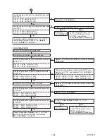
FLOW CHART NO.21
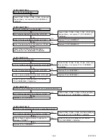
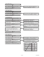
Audio is not outputted during playback.
Set the disc on the disc tray, and playback.
IC1201 7PIN AUDIO (L)-OUT
IC1201 1PIN AUDIO (R)-OUT
Replace P1(AV ASSEMBLY).
Are the analog audio signals outputted to each pin
of IC1201?
Yes
No
Check the periphery between Pin(1,7) of IC1201
and the audio terminal (JK2201), and replace
P1(AV ASSEMBLY) if defective.
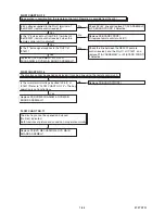
IC1022 14PIN AUDIO (L)-OUT
IC1022 4PIN AUDIO (R)-OUT
Are the analog audio signals outputted to each pin
of IC1022?
No
Yes
Is the "L" pulse inputted to Pin (9, 10, 11) of IC1022?
Replace P1
(AV ASSEMBLY).
Check the line between Pin (9,
10, 11) of IC1022 and Pin (37)
of IC1501, and replace
P1(AV ASSEMBLY) if defective.
Yes
No
C
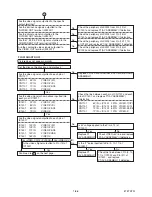
IC1201 7PIN AUDIO (L)-OUT
IC1201 1PIN AUDIO (R)-OUT
Replace P1(AV ASSEMBLY).
Are the analog audio signals outputted to each pin
of IC1201?
Yes
No
Check the periphery between Pin(1,7) of IC1201
and the audio terminal (JK2201), and replace
P1(AV ASSEMBLY) if defective.
IC1022 14PIN AUDIO (L)-OUT
IC1022 4PIN AUDIO (R)-OUT
Are the analog audio signals outputted to each pin
of IC1022?
No
Yes
Is the "L" pulse inputted to Pin (9, 10, 11) of
IC1022?
Replace P1
(AV ASSEMBLY).
Check the line between Pin (9,10,
11) of IC1022 and Pin (37) of
IC1501, and replace
P1(AV ASSEMBLY) if defective.
Yes
No
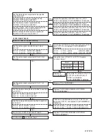
Are the analog audio signals outputted to each pin
of CN1101?
CN1101 15PIN AUDIO (L)-OUT
CN1101 13PIN AUDIO (R)-OUT
Yes
No
Replace P2(DVD MECHANISM & DVD MAIN BOARD
ASSEMBLY).
IC1201 6PIN AUDIO (L)-OUT
IC1201 2PIN AUDIO (R)-OUT
Check each line between each pin of CN1101 and
each pin of IC1201, and replace P1(AV ASSEMBLY)
if defective.
CN1101 15PIN
→
IC1201 6PIN AUDIO(L)-OUT
CN1101 13PIN
→
IC1201 2PIN AUDIO(R)-OUT
Are the analog audio signals inputted to each pin
of IC1201?
Yes
No
No
Do Pin(16) of CN1101 become "H" level?
Replace P2(DVD MECHANISM & DVD MAIN BOARD
ASSEMBLY).
Summary of Contents for D-R410KU
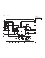
Page 35: ...1 11 4 AV 2 4 Schematic Diagram E7K7ASCAV2 NOTE BOARD MEANS PRINTED CIRCUIT BOARD ...
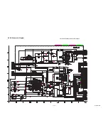
Page 36: ...1 11 5 E7K7ASCAV3 AV 3 4 Schematic Diagram NOTE BOARD MEANS PRINTED CIRCUIT BOARD ...
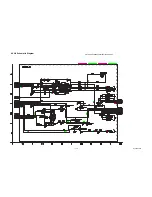
Page 37: ...1 11 6 E7K7ASCAV4 AV 4 4 Schematic Diagram NOTE BOARD MEANS PRINTED CIRCUIT BOARD ...
Page 45: ...1 11 14 DVD Main 6 7 Schematic Diagram E7K7ASCD6 NOTE BOARD MEANS PRINTED CIRCUIT BOARD ...
Page 47: ...1 11 16 BE7K2AF01011A BOARD AV Top View NOTE BOARD MEANS PRINTED CIRCUIT BOARD ...
Page 56: ...1 14 3 R5NTI Push close 0 08 V 0 02 s Push Close detection Threshold level ...
Page 66: ......

