3-12
3.8 Replacing the Black Mark Sensor Ass’y
1. Please refer to 3.1 for disassembling the lower cover ass’y and lower inner
cover.
2. Disconnect all harnesses from the main PCB ass’y .
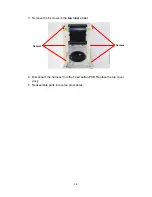
3. Turn the lower inner cover upside down. Remove 4 screws and remove the
plastic laminate
.
4. Remove 1 screw from the
black mark sensor ass’y
.
5. Turn over the lower inner cover.
6. Replace the
black mark sensor ass’y
.
7. Reassemble parts in reverse procedures.
8. After exchanging the black mark sensor ass’y, do the calibration based on
Section 2.9.1Media sensor in the Owner’s Manual as a reference
Screw
Black Mark Sensor Ass’y
Lower Inner
Cover
Black Mark Sensor
Ass’y
Lower Inner
Cover
Fixing Plate
Summary of Contents for B-SV4T
Page 15: ...2 3 2 2 MCU Circuit and MCU PIN Description Fig 5 MCU PIN Description Diagram ...
Page 16: ...2 4 2 2 1 MCU PIN Description ...
Page 17: ...2 5 ...
Page 18: ...2 6 ...
Page 19: ...2 7 ...
Page 23: ...2 11 2 5 Decoder Circuit Fig 8 Decode Circuit Diagram ...
Page 32: ...2 20 2 12 USB Circuit Fig 14 USB Circuit Diagram ...
Page 33: ...2 21 2 12 1 USB PIN Function The standard USB 1 1 PIN function is as following ...
Page 34: ...2 22 ...
Page 46: ...3 6 4 Replace the main PCB ass y 5 Reassemble parts in reverse procedures ...
Page 59: ...4 2 4 Revert the memory module cover 5 Reassemble parts in reverse procedures ...
Page 71: ...E PRINTED IN JAPAN EO18 33019 ...


