background image


2-9

2.3 Reset Circuit 


Fig. 6    Reset Circuit Diagram 


S-80845 IC voltage detector can detect the voltage while RC is charging and 

output the system reset signal of 

low

 when the driving voltage is lower than 4.5Vdc 

(Typical). 


Summary of Contents for B-SV4T

Page 1: ... JAPAN TOSHIBA Barcode Printer B SV4T SERIES Document No EO18 33019 Original Jun 2007 Revised Printer Manual This manual includes the contents of the Product Descrption Maintenance Manual and Circuit Description ...

Page 2: ... 13 2 8 Stepping Motor Driver Protection Circuit 2 14 2 9 Power Circuit 2 16 2 10 Parallel Interface Circuit 2 17 2 11 Serial Interface Circuit 2 19 2 12 USB Circuit 2 20 2 12 1 USB PIN Function 2 21 2 13 Sensor Circuit 2 23 2 13 1 Feed Gap and Black Mark Sensor 2 23 2 13 2 Head Open Micro Switch 2 24 2 13 3 Strip Sensor 2 25 2 13 4 Ribbon Sensor 2 26 2 14 Cutter Drive Protection Circuit 2 27 2 15...

Page 3: ...704 E1M E2M E3M E4M E6M E8M QM R 4 1 4 2 Install the Strip Module Option B SV404 H QM R 4 3 4 3 Install the Cutter Module Option B SV204 QM R 4 5 5 TROUBLESHOOTING 5 1 6 MAINTENANCE 6 1 CAUTION 1 This manual may not be copied in whole or in part without prior written permission of TOSHIBA TEC 2 The contents of this manual may be changed without notification 3 Please refer to your local Authorised ...

Page 4: ...ar View Fig 1 2 Rear View Top Cover Cover Open Lever FEED PAUSE Button Media Outlet Indicator Lamp Ribbon Access Cover Power Jack Power Switch Parallel Interface Connector Centronics Serial Interface Connector RS 232C Label Roll Capacity View Window Rear Media Guide USB Interface Connector ...

Page 5: ...transfer Print width 4 4 inches Media Guide Feed Gap Sensor Black Mark Sensor Print Head Media Hold Shaft Cover Open Sensor Caution Symbol for the Print Head Please refer to WARNING Top Cover Support Platen Rear Hub Front Hub Strip Plate Ribbon Access Ribbon Sensor Media Guide WARNING Do not touch the print head or around it just after printing You may get burned as the print head becomes very hot...

Page 6: ...ge Reflective sensor position adjustable Head open sensor Ribbon sensor Memory 1M byte Flash memory 2M bytes DRAM Interface RS 232C max baud rate 57600 bps USB V1 1 Centronics SPP mode Power AC input 100 240V universal auto switching power supply DC output 24V 3 75A Firmware Font Type 8 alpha numeric bitmap fonts and 1 true type font Rotation 0 90 180 and 270 degrees Barcode Format Code 39 Code 93...

Page 7: ...ia Roll Hanger is used Roll direction Outside Inner core diameter 25 4 38 1 or 76 2 1 1 5 or 3 See NOTE 2 Note 1 To ensure print quality and print head life use only TOSHIBA TEC approved media 2 When using a media roll of 76 2 mm 3 inner core diameter the 3 Diameter Media Shaft included in the optional External Media Roll Hanger is required 3 The width and thickness quoted above are said of the la...

Page 8: ... transmissive sensor is located in the right side of label guide which detects at 6 mm from the liner edge of media the detectible range at least offset 6 mm Regarding the label the detectible function only can be used at this way The minimun lengh of gap is 2 mm and the the detectible range is 8 mm ...

Page 9: ...ion The reflective sensor is full range moveable for detecting the black mark and nutchf The scope of black mark length detection is min 2 0 mm max 3 81 mm and min black mark width 8mm Figure 3 Black Mark Detection Figure 4 ...

Page 10: ...is 0 76mm 0 030 3 Attached hole maybe used as a black mark sensor Oval Rectangular attached hole is recommended Rectangular Aperture Detection If the rectangular aperture located at the center of label tag please use the reflective sensor Inside of the up cover has a Black Mark this is aimed for aperture or transparent label tag Figure 5 ...

Page 11: ...iameter of core Max outside diameter 67 mm Outside diameter of core 25 7 0 3 mm Roll direction Outside End tape Polyester film transparent or silver film opaque 250 5 mm long NOTICE 1 Ribbon sensor is reflective sensor Transparent film or light reflection silver film is recommended in the end of ribbon 2 The maximum length of ribbon depends on its thickness and core outside diameter The formula be...

Page 12: ...ble indicates a number corresponding to the ribbon width 1 This cannot be used when a serial bar code is printed and print density should be lower at 40 degree 2 This cannot be used when a serial bar code is printed at 5 inch per sec Ribbon model name Brand TR45 Fuji Copian DW 350 DNP AWR 470 ARMOR B 110A RICOH B 110C RICOH TR4085 Sony Chemical TR4065 Sony Chemical TR4070 Sony Chemical Core ...

Page 13: ...ig 3 Circuit Diagram The main PCB ass y of printer includes 10 system blocks 1 MCU 2 Memory System 3 Decoder System 4 Print Head System 5 Motor System 6 Power System 7 Communication Interface System 8 USB System 9 Sensor System 10 Cutter System ...

Page 14: ...ing figure shows the PCB system areas Fig 4 PCB System Areas Diagram Sensor System Cutter System Memory System Motor System Print Head System Power System Decoder System Communication Interface System USB System MCU ...

Page 15: ...2 3 2 2 MCU Circuit and MCU PIN Description Fig 5 MCU PIN Description Diagram ...

Page 16: ...2 4 2 2 1 MCU PIN Description ...

Page 17: ...2 5 ...

Page 18: ...2 6 ...

Page 19: ...2 7 ...

Page 20: ...used input pins should be pulled up or pulled down 2 The WDTOVF pin should be pulled down in the SH7044 SH7045 F ZTAT version However if it is necessary to pull this pin down a resistance of 100 k or higher should be used ...

Page 21: ...Reset Circuit Fig 6 Reset Circuit Diagram S 80845 IC voltage detector can detect the voltage while RC is charging and output the system reset signal of low when the driving voltage is lower than 4 5Vdc Typical ...

Page 22: ...e are 2MB DRAM and 2MB flash ROM built on main PCB ass y It uses U6 U7 type 1M Byte Flash ROM and U8 type 2M Byte DRAM MCU R W pin becomes high when reading Flash ROM or DRAM and becomes low when writing JP6 is memory module connector which can expand to 8MB ...

Page 23: ...2 11 2 5 Decoder Circuit Fig 8 Decode Circuit Diagram ...

Page 24: ... RTC register data 00C0 0000 I O 00D8 0000 RTC register address 00D0 0003 ECP 00D0 0002 Ribbon Sensor value 00D0 0001 Black mark sensor value 0080 0000 Memory module 00D0 0000 Feed Gap sensor Value 00C8 0003 Buzzer 00C8 0002 Reserved 00C8 0001 Mem_load signal 0040 0000 Memory module 00C8 0000 Cutter Control 00C0 0003 Motor Current 00C0 0002 USB Data 0010 0000 ROM2 00C0 0001 Centronic Control 0000 ...

Page 25: ... used to make sure the power of print head is off when switch off the printer Q1 and Q2 are used to limit current of print head Both STB1 and STB2 determine whether to heat the thermal head or not The RC charging time of U15 and 74HC123 limit the heating time of print head to avoid burning the print head DI signal sends printer data to the print head TM signal is the temperature voltage sensor for...

Page 26: ...stepping motor power level The power level pattern is shown in table2 The motor port is a protection pin When it is at low level the power of the motor system will be closed Power will be on again until motor pin is the pulse of high level Phase1 and phase2 determine the pattern of stepping motor drive circuit For example the sequence of phase 1 phase 2 in full step mode is 0 0 0 1 1 1 1 0 ...

Page 27: ...tern Step Pin on JP12 1 2 3 4 Phase 1 on on on A 2 on on A 3 on on on B 4 on on B Table 2 Stepping motor power pattern Motor Current Current percentage I0 I1 High Level 100 L L Medium Level 60 H L Low Level 20 L H Zero Current 0 H H ...

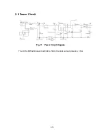
Page 28: ...2 16 2 9 Power Circuit Fig 11 Power Circuit Diagram The U3 SI 8050JD converts 24Vdc to 5Vdc the limit current protest is 1 6A ...

Page 29: ... SPP mode or ECP mode The parallel interface circuit is used with the externally connected personal computer parallel interface through the printer cable When PC s strobe signal comes in the printer responds busy status until it reads the data from parallel interface Printer will respond error signal to PC when it is in error status ...

Page 30: ...sy Out When in reverse direction a high indicates data while a low indicates a command cycle In forward direction it functions as PtrBusy 12 Paper Out End AckDataReq Out When low device acknowledges reverse request 13 Select X Flag Out Extensibility flag 14 Auto Linefeed HostBusy In When in forward direction a high indicates data while a low indicates a command cycle In reverse direction it functi...

Page 31: ...h externally connected personal computer and keyboard unit JP15 connects to PC serial interface through the RS 232 cable RxD is a data receive pin of MCU CTS is clear to send of MCU which sends a signal from the external device TxD is a data output pin of MCU RTS is the request to send signal which sends signal to the external device ...

Page 32: ...2 20 2 12 USB Circuit Fig 14 USB Circuit Diagram ...

Page 33: ...2 21 2 12 1 USB PIN Function The standard USB 1 1 PIN function is as following ...

Page 34: ...2 22 ...

Page 35: ... Mark Sensor Circuit Diagram 1 The feed gap sensor is a penetrable sensor with 64 levels 2 Black mark sensor is a reflecting sensor with 64 levels 3 The feed gap sensor activates when feed gap and black mark SW signal is high The black mark sensor activates when GAP BM_SW signal is low ...

Page 36: ...2 24 2 13 2 Head Open Micro Switch Fig 16 Head Open Micro Switch Circuit Diagram The Head Open Micro Switch is a micro switch The voltage is low when the print head opens otherwise it is high ...

Page 37: ...2 25 2 13 3 Strip Sensor Fig 17 Strip Sensor Circuit Diagram This is a reflecting sensor The strip sensor signal voltage is high when the paper is detected otherwise it is low ...

Page 38: ...ensor Fig 18 Ribbon Sensor Circuit Diagram This ribbon sensor is a reflecting sensor The RIBB1 3 can be changed by command or auto calibration The REND signal voltage is high when the ribbon is detected otherwise it is low ...

Page 39: ...s high when the printer is turned on The cutter is activated when CTEN signal is low CTPhase signal controls the rotated direction U15B 74HC123 controls the breaking of the DC motor of the cutter The sensor of the cutter sends high low signal to MCU through the CTSENS pin that detects action of a cutter ...

Page 40: ...cuit Diagram DCM signal is used to switch on off the motor driver The DC PHASE signal is to control the direction of the rotate the encoder circuit which is used to detect the rotary rate DC SENS signal voltage is high when the hole of the gear is detected otherwise it is low ...

Page 41: ...ing any parts 2 Follow all manual instructions Failure to do so could create safety hazards such as fire or electrocution NOTES 1 Manual instructions must be followed when installing option kits or adding cables to avoid system failures and to insure proper performance and operation 2 Failure to follow manual instructions or any unauthorized modifications substitution or change to this product wil...

Page 42: ...cover 2 Open the top cover to the ultimate angle Push the top cover support to the communication port direction to separate the lower inner cover and top cover Top cover support Top cover open lever CAUTION 1 NEVER touch the element when handling the Print Head 2 NEVER touch the connector pins to avoid a breakdown of the Print Head by static electricity Top cover ass y Top cover open lever ...

Page 43: ...3 3 3 Remove the 6 screws in the top inner cover 4 Disconnect the harness from the Feed button PCB Replace the top cover ass y 5 Reassemble parts in reverse procedures Screws Screws ...

Page 44: ... printer upside down remove the 2 screws of hinge holder and 1 screw of memory module cover 3 Disconnect all harnesses from Main PCB ass y Lift up the lower inner cover 4 Replace the lower inner cover 5 Reassemble in reverse procedures Lower inner cover Screws Screws Memory module cover Screw Screw of hinge holder Screw of hinge holder ...

Page 45: ...ct all harnesses from Main PCB ass y Lift up the lower inner cover 4 Replace the lower cover ass y 5 Reassemble in reverse procedures 3 4 Replacing the Main PCB Ass y 1 Please refer to 3 2 3 3 for disassembling the lower cover ass y and lower inner cover 2 Disconnect all harnesses from the main PCB ass y 3 Remove 4 screws on the main PCB ass y Screw Screw Screw Screw Lower Cover Ass y Main PCB Ass...

Page 46: ...3 6 4 Replace the main PCB ass y 5 Reassemble parts in reverse procedures ...

Page 47: ...3 7 3 5 Replacing the Platen Ass y 1 Squeeze two sides of platen ass y and take it out 2 Replace a platen ass y 3 Reassemble it in reverse procedures Squeeze Here Platen Ass y Squeeze Here ...

Page 48: ...ss y and lower inner cover 2 Disconnect all harnesses from the main PCB ass y 3 Turn the lower inner cover upside down 4 Remove 2 screws that fixed the stepping motor on the bracket 5 Remove the stepping motor 6 Remove 8 screws of the stepping motor bracket metal assembly Screws Screws Screws Stepping Motor Motor Bracket Metal Assembly ...

Page 49: ...3 9 7 Remove the motor bracket metal assembly 8 Reassemble parts in reverse procedures Motor Bracket Metal Assembly ...

Page 50: ...esses from the main PCB ass y 3 Turn the lower inner cover upside down 4 Screws off 4 screws and remove the plastic laminate 5 Screws off 2 screws from a Label Guide Rack Fixing Plate and 2 from a gap sensor PCB then remove the feed gap sensor ass y Screws Screws Screw Screw Feed Gap Sensor Ass y Plastic Laminate Lower Inner Cover Label Guide Rack Fixing Plate Screw ...

Page 51: ...bel guides to the end of each side Rotates 90 degrees and pull them out 8 Reassemble parts in reverse procedures 9 After exchanging the feed gap sensor ass y do the calibration based on Section 2 9 1Media sensor in the Owner s Manual as a reference Label Guides Lower Inner Cover ...

Page 52: ...ws and remove the plastic laminate 4 Remove 1 screw from the black mark sensor ass y 5 Turn over the lower inner cover 6 Replace the black mark sensor ass y 7 Reassemble parts in reverse procedures 8 After exchanging the black mark sensor ass y do the calibration based on Section 2 9 1Media sensor in the Owner s Manual as a reference Screw Black Mark Sensor Ass y Lower Inner Cover Black Mark Senso...

Page 53: ...er head bracket then pick up the print head ass y 2 Disconnect print head harnesses 3 Reassemble parts in reverse procedures Print Head Ass y CAUTION 1 NEVER touch the element when handling the Print Head Ass y 2 NEVER touch the connector pins to avoid a breakdown of the Print Head by static electricity Bracket Concave Stick Flat Screwdriver Here ...

Page 54: ...he top cover ass y and top inner cover 2 Disconnect ribbon drive block by screwing off 4 screws at top inner cover 3 Remove 2 screws and remove the head open micro switch 4 Reassemble parts in reverse procedures Screws Head Open Micro Switch Ribbon Drive Block Screws Screws Top Inner Cover ...

Page 55: ... for disassembling the top cover ass y and top inner cover 2 Disconnect ribbon drive block by screwing off 4 screws at top inner cover 3 Screw off 2 screws at side of the ribbon mount 4 Replace the ribbon motor sensor Screws Screws Screws Ribbon Motor Sensor Ribbon Drive Block ...

Page 56: ...3 16 5 Screw off 2 screws from the top inner cover 6 Replace the ribbon sensor 7 Reassemble parts in reverse procedures Screws Ribbon Sensor ...

Page 57: ... refer to 3 1 for disassembling the top cover ass y and top inner cover 2 Turn the top cover upside down 3 Remove 2 screws on feed button Ass y and remove feed button PCB 4 Reassemble parts in reverse procedures Screws Feed Button Ass y Top Cover Ass y ...

Page 58: ...Set Up Memory Module Option B SV704 E1M E2M E3M E4M E6M E8M QM R 1 Turn the printer upside down 2 Screw off 1 screw and open the memory module cover 3 Plug in a memory module pin to pin on main PCB ass y Memory Module Screw Memory Module Cover Main PCB Ass y ...

Page 59: ...4 2 4 Revert the memory module cover 5 Reassemble parts in reverse procedures ...

Page 60: ... y and lift up the top cover open levers to separate the lower inner cover and the lower cover ass y Please refer to section 3 1 5 Connect the harness of strip module through the slot of lower inner cover 6 Lift up the lower inner cover to gently push strip panel into the two concaves of lower cover front side Note Must lift up the lower inner cover first then the strip module could be installed i...

Page 61: ...JP17 on the main PCB ass y 8 Put down the lower inner cover onto lower cover ass y 9 Push strip module to lock to the lower inner cover 10 Reassemble parts in reverse procedures Lower Cover Ass y Lower Inner Cover Strip Module Main PCB Ass y JP17 ...

Page 62: ...f hinge holder in the lower cover ass y 2 Remove the screw that fixes the memory module cover Screw of hinge holder Screw of hinge holder Memory module Cover 1 Be sure to turn OFF the power before removing the Cutter Cover 2 Care must be taken not to injure your fingers by the cutter blade WARNING Screw ...

Page 63: ...will hold the printer top cover ass y 5 Open the top cover ass y to the ultimate open angle Push the top cover support to the communication port direction to disconnect the lower inner cover and top cover support 6 Pull up the front cover from the lower cover ass y 7 Remove the 6 screws in lower inner cover 8 Lift up the lower inner cover from the lower cover ass y Cutter Driver IC A3952SB Front C...

Page 64: ...connector of the cutter onto JP10 on the main PCB ass y Pull the wire of the 4 pin connector through the slot of lower inner cover front side Then put back the lower inner cover Location JP10 Cutter wire Slot wire of the 4 pin ...

Page 65: ...ter module into the two slots of lower inner cover front side then push cutter to lock into the lower inner cover 11 Assemble the memory module cover 12 Reassemble parts in reverse procedures Lower inner cover Cutter Module ...

Page 66: ...following and then press the feed button to resume printing 1 Insert a paper roller into a paper roll 2 Open the printer s top cover by releasing the green cover lock tabs located on each side of the printer and lifting the top cover A support bar at the rear of the printer will hold the printer top cover open 3 Place a roll of paper onto the center of the paper roll mount 4 Feed the paper printin...

Page 67: ...ically If the printer LED is still on red blink please check the following A Is a paper core installed on the ribbon rewind spindle B Is ribbon installed correct along the ribbon path C Is the ribbon too transparent D Is the rib of the ribbon spindle is broken E Is the ribbon gear broken or worn F Turn off printer power Rewind the ribbon spindle by hand Does the spindle rewind smoothly by hand If ...

Page 68: ...of Initialization in Interface Specification to reset the system 6 Continuous feeding labels The printer setting may go wrong Please do the Initialization and Feed Gap and Black Mark Sensor Calibration Refer to Interface Specification 7 No print on the label Is the label or ribbon loaded correctly Refer to No 4 Label runs out and Ribbon runs out to load the paper or to load the ribbon Does the rib...

Page 69: ... Please replace a new main PCB ass y 12 Cutter functions abnormally Cutter is not activated Cutter is broken or the main PCB ass y is broken If it still has problem after a new cutter replaced the U14 driver IC or U5 IC on the main PCB ass y may be broken 13 Black mark can t be detected properly Please check the position of the black mark Is the width of black mark too thin to be detected The sugg...

Page 70: ...aintain your printer Use one or more of the following supplies that meets your needs Cleaning pens Cleaning swabs Lint free cloth The cleaning process is described as following Printer Part Method Printer Head Let the print head to cool for one minute Use a cleaning pen to swab the print elements Platen Roller Rotate the platen roller and wipe it thoroughly with 70 ethanol and a cleaning swab or l...

Page 71: ...E PRINTED IN JAPAN EO18 33019 ...

Reviews: