background image

User’s Manual

3-3

A350/A350D

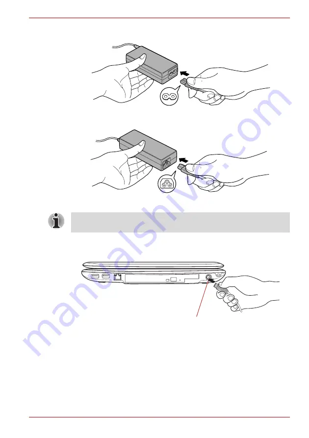
1. Connect the power cord to the AC adaptor.

Figure 3-1 Connecting the power cord to the AC adaptor (2-pin plug)

Figure 3-2 Connecting the power cord to the AC adaptor (3-pin plug)

2. Connect the AC adaptor’s DC output plug to the DC IN 19V jack on the 

right side of the computer.

Figure 3-3 Connecting the adaptor to the computer

3. Plug the power cord into a live wall outlet - the 

Battery

 and 

DC IN


indicators on the front of the computer should glow.

Either a 2-pin or 3-pin adaptor/cord will be included with the computer 
depending on the model.

DC IN 19V Jack

Summary of Contents for A355-SC2902

Page 1: ...computers toshiba europe com User s Manual A350 A350D ...

Page 2: ...h the display closed 2 1 Left side 2 3 Right side 2 5 Back side 2 6 Underside 2 6 Front with the display open 2 8 Front operation panel 2 11 System indicators 2 12 Optical disc drives 2 14 AC adaptor 2 15 Chapter 3 Getting Started Connecting the AC adaptor 3 2 Opening the display 3 4 Turning on the power 3 5 Starting up for the first time 3 5 Turning off the power 3 6 Restarting the computer 3 10 ...

Page 3: ...apter 5 The Keyboard Typewriter keys 5 1 Function keys F1 F12 5 2 Soft keys FN key combinations 5 2 Hot keys 5 3 Windows special keys 5 5 Keypad overlay 5 6 Generating ASCII characters 5 7 Chapter 6 Power and Power up Modes Power conditions 6 1 Power indicators 6 2 Battery 6 3 Care and use of the battery pack 6 5 Replacing the battery pack 6 9 TOSHIBA Password Utility 6 11 Power up modes 6 13 Chap...

Page 4: ... solving process 9 1 Hardware and system checklist 9 3 TOSHIBA support 9 24 Chapter 10 Disclaimers Appendix A Specifications Environmental requirements A 1 Appendix B Display Controller Appendix C Wireless LAN Card Specifications C 1 Radio Characteristics C 2 Supported Frequency Sub bands C 3 Appendix D AC Power Cord and Connectors Certification agencies D 1 Appendix E If your computer is stolen G...

Page 5: ...idated and reviewed for accuracy The instructions and descriptions it contains are accurate for the TOSHIBA A350 A350D Portable Personal Computers at the time of this manual s production However succeeding computers and manuals are subject to change without notice TOSHIBA assumes no liability for damages incurred directly or indirectly from errors omissions or discrepancies between the computer an...

Page 6: ...lectual property rights including U S Patent Numbers 6 836 549 6 381 747 7 050 698 6 516 132 and 5 583 936 Use of this copyright protection technology must be authorized by Macrovision and is intended for home and other viewing uses only unless otherwise authorized by Macrovision Reverse engineering or disassembly is prohibited The copyright protection technology availability depends on the model ...

Page 7: ...e products plugged in to the extension cable does not exceed the ampere rating of the extension cable To remove power from the computer turn it off remove the battery and disconnect the AC adaptor from the electrical outlet To help avoid the potential hazard of electric shock do not connect or disconnect any cables or perform maintenance or reconfiguration of this product during an electrical stor...

Page 8: ...e mentioned Residential commercial and light industry environments For example the following environments are not approved Industrial Environments e g environments where a mains voltage of 380 V three phase is used Medical Environments Automotive Environments Aircraft Environments Any consequences resulting from the use of this product in working environments that are not approved are not the resp...

Page 9: ... with the following networks It has been tested to and found to conform with the additional requirements conditional in EG 201 121 Specific switch settings or software setup is required for each network please refer to the relevant sections of the user guide for more details The hookflash timed break register recall function is subject to separate national type approvals It has not been tested for...

Page 10: ...pe com or contact your local city office or the shop where you purchased the product The crossed out wheeled dust bin symbol indicates that batteries and or accumulators must be collected and disposed of separately from household waste If the battery or accumulator contains more than the specified values of lead Pb mercury Hg and or cadmium Cd defined in the Battery Directive 2006 66 EC then the c...

Page 11: ...onserve energy your computer is set to enter the low power Sleep mode which shuts down the system and display within 15 minutes of inactivity in AC power mode TOSHIBA recommends that you leave this and other energy saving features active so that your computer will operate at its maximum energy efficiency You can wake the computer from Sleep mode by pressing the power button Products that earn the ...

Page 12: ...er 21 Standards of the Department of Health and Human Services DHHS 21 CFR For any other country the drive is certified to meet the Class 1 Laser standards of IEC825 and EN60825 Optical disc drive safety instructions The drive employs a laser system To ensure proper use of this product please read this instruction manual carefully and retain for future reference Should the unit ever require mainte...

Page 13: ... WITH FDA RADIATION PERFORMANCE STANDARDS 21 CFR SUBCHAPTER J MANUFACTURED Panasonic Communications Co Ltd 1 62 4 Chome Minoshima Hakata ku Fukuoka Japan Location of the required label COMPLIES WITH FDA RADIATION PERFORMANCE STANDARDS 21 CFR SUBCHAPTER J MANUFACTURED Hitachi LG Data Storage Inc 22 23 Kaigan 3 chome Minato Ku Tokyo 108 0022 Japan ...

Page 14: ...APTER J MANUFACTURED PIONEER CORPORATION 4 1 MEGURO 1 CHOME MEGURO KU TOKYO 153 8654 JAPAN Location of the required label PRODUCT IS CERTIFIED BY THE MANUFACTURER TO COMPLY WITH DHHS RULES 21 CFR CHAPTER 1 SUBCHAPTER J APPLICABLE AT THE DATE OF MANUFACTURE MANUFACTURED Toshiba Samsung Storage Technology Korea Corporation 416 Maetan 3Dong Yeongtong Gu Suwon City Gyeonggi Do 443 742 Korea ...

Page 15: ...tung sorgfältig durch und bewahren diese bitte als Referenz auf Falls Probleme mit diesem Modell auftreten benachrichtigen Sie bitte die nächste autorisierte Service Vertretung Um einen direkten Kontakt mit dem Laserstrahl zu vermeiden darf das Gerät nicht geöffnet werden ADVARSEL Denne mærking er anbragt udvendigt på apparatet og indikerer at apparatet arbejder med laserstråler af klasse 1 hviket...

Page 16: ... in this manual Replace only with the same or equivalent type battery recommended by the manufacturer Dispose of used batteries according to the manufacturer s instructions OBS Apparaten innehåller laserkomponent som avger laserstråining överstigande gränsen för laserklass 1 VAROITUS Suojakoteloa si saa avata Laite sisältää laserdiodin joka lähetää näkymätöntä silmilie vaarallista lasersäteilyä CA...

Page 17: ... user please continue reading the preface to learn how this manual is organized then become acquainted with this manual by browsing through its pages Be sure to read the Special features section of the Introduction to learn about features that are uncommon or unique to the computers and carefully read HW Setup If you are going to install ExpressCards or connect external devices such as a printer b...

Page 18: ...e technical information about your computer The Glossary defines general computer terminology and includes a list of acronyms used in the text The Index quickly directs you to the information contained in this manual Conventions This manual uses the following formats to describe identify and highlight terms and operating procedures Abbreviations On first appearance and whenever necessary for clari...

Page 19: ...ows ABC When procedures require an action such as clicking an icon or entering text the icon s name or the text you are to type in is represented in the typeface you see to the left ABC Names of windows or icons or text generated by the computer that appear on its display screen are presented in the type face you see to the left Pay attention A caution informs you that improper use of equipment or...

Page 20: ...ough space around the computer and other equipment to provide adequate ventilation Otherwise they may overheat To keep your computer in prime operating condition protect your work area from Dust moisture and direct sunlight Equipment that generates a strong electromagnetic field such as stereo speakers other than speakers that are connected to the computer or speakerphones Rapid changes in tempera...

Page 21: ...ensitive to heat as the material could become damaged Pressure or impact damage Do not apply heavy pressure to the computer or subject it to any form of strong impact as this can damage the computer s components or otherwise cause it to malfunction ExpressCard overheating Some ExpressCards can become hot during prolonged use which may result in errors or instability in the operation of the device ...

Page 22: ...xxii User s Manual A350 A350D ...

Page 23: ... or 3 pin plug Cleaning cloth included with some models Software The following Windows operating system and utility software are pre installed Microsoft Windows Vista Modem Driver Can be used only for Modem models Bluetooth Driver Can be used only for Bluetooth models Display Driver for Windows TOSHIBA Value Added Package TOSHIBA Hardware Setup TOSHIBA Supervisor Password Some of the features desc...

Page 24: ...es TOSHIBA Assist TOSHIBA CD DVD Drive Acoustic Silencer TOSHIBA DVD PLAYER Online Manual Documentation TOSHIBA A350 A350D Portable Personal Computer User s Manual TOSHIBA A350 A350D Quickstart Instruction Manual for Safety and Comfort Warranty information If any of the items are missing or damaged contact your dealer immediately SD Memory Card Format Utility and other SD functions are packaged in...

Page 25: ...e depending on the model you purchased If your computer is configured with two 2 GB memory modules or more the memory might be displayed as approximately 3 GB only depending on the computer s hardware specifications This is correct because the operating system usually displays the available memory instead of the physical memory RAM built into the computer Various system components like the video a...

Page 26: ... main memory and the proportion depends on Dynamic Video Memory Technology Mobile Intel GM45 Express Chipset model Mobile Intel PM45 Express Chipset model in graphic chip by ATI Mobility Radeon HD 3470 External 256MB Mobile Intel GM45 Express Chipset model Mobile Intel PM45 Express Chipset model in graphic chip by ATI Mobility Radeon HD 3650 External 512MB AMD M780G Chipset model Video RAM capacit...

Page 27: ... in The internal keyboard provides the embedded numeric overlay keys dedicated cursor control overlay keys and Keys The keyboard is compatible with the IBM enhanced keyboard Refer to Chapter 5 The Keyboard for details Built in Touch Pad The integrated Touch Pad and control buttons in the palm rest allow control of the on screen pointer and support functions such as the scrolling of windows Battery...

Page 28: ... VGA port This port allows you to connect an external monitor to the computer Universal Serial Bus USB 2 0 The computer supports multiple Universal Serial Bus ports that comply with the USB 2 0 standard The ports with the has a USB Sleep and Charge function One of the USB ports has an eSATA External Serial ATA function i LINK IEEE1394 This port allows high speed data transfer to take place between...

Page 29: ...e HDMI cable can send video and audio signals In addition to this it can send and receive control signals By connecting a TV which supports HDMI Control to this port the remote control for the connected TV can be used to operate some of the computer functions Refer to the REGZA Link PC Control section in Chapter 8 Optional Devices for more details Headphone S PDIF jack This jack lets you connect d...

Page 30: ...s between electronic devices such as computers and printers and mobile phones When it is enabled Bluetooth provides the wireless personal area network environment which is safe and trustworthy that is quick and easy Wireless LAN Some computers in this series are equipped with a Wireless LAN module that is compatible with other LAN systems based on Direct Sequence Spread Spectrum Orthogonal Frequen...

Page 31: ... CD ROM s at a maximum 24x speed and writes CD R s at up to 24x speed CD RW s at up to 24x speed DVD R s and DVD R s at up to 8x speed DVD RW s and DVD RW s at up to 8x speed DVD R Dual layer discs at up to 6x speed DVD R Double Layer discs at up to 6x speed and DVD RAM s at up to 5x speed and supports the following formats CD R CD RW DVD ROM DVD Video CD DA CD Text Photo CD single multi session C...

Page 32: ... s at up to 24X speed and CD RW s at up to 24X speed DVD R s DVD R s and DVD RW s at up to 8x speed DVD RW s at up to 8X speed DVD R Dual Layer discs and DVD R Double Layer discs at up to 6x speed and DVD RAMs at up to 5x speed This drive supports the same formats as the DVD Super Multi drive Operating system Microsoft Windows Vista is available Refer to the preinstalled software section at the fr...

Page 33: ...d Please refer to the Keypad overlay section in Chapter 5 The Keyboard for information on using this feature Power on password Two levels of password security supervisor and user are available to prevent unauthorized access to your computer Instant security A specific hot key function automatically locks the system providing data security Intelligent power supply 1 A microprocessor in the computer...

Page 34: ...software The contents of main memory are automatically saved to the hard disk drive so that when you next turn the power on again you can continue working right where you left off Sleep Mode If you have to interrupt your work you can use this feature to allow you to turn off power to the computer without exiting from your software Data is maintained in the computer s main memory so that when you n...

Page 35: ... utility provides support to movement impaired users when they need to use the TOSHIBA Hot key functions In use the utility allows you to make t3he FN key sticky that is you can press it once release it and they press one of the F keys in order to access its specific function When set the FN key will remain active until another key is pressed TOSHIBA Face Recognition TOSHIBA Face Recognition uses ...

Page 36: ...reate CD s and DVD s in a number of formats including audio CD s that can be played on a standard CD player and data CD s DVD s which can store copies of the files and folders on your computer s hard disk drive To start this utility click Start All Programs TOSHIBA CD DVD Applications Disc Creator TOSHIBA DVD RAM Utility This utility has the function of Physical Format and Write Protect to DVD RAM...

Page 37: ...obility Center is a utility for accessing several mobile PC settings quickly in one window A default maximum of eight tiles are provided by the operating system and the additional two tiles are added to your Mobility Center Lock Computer This can be used to lock your computer without turning it off This has the same function as the Lock button at the bottom of the right pane in the start menu TOSH...

Page 38: ... memory module DDR2 800 can easily be installed in the computer Battery Pack An additional battery pack can be purchased for use as either a spare or replacement Please refer to Chapter 6 Power and Power up Modes for futher information AC Adaptor If you frequently use your computer at more than one site it may be convenient to purchase an additional AC adaptor to be kept at each site in order to r...

Page 39: ...ng figure shows the computer s front with its display panel in the closed position Figure 2 1 Front of the computer with display closed Wireless communication switch Headphone S PDIF jack Bridge media slot Microphone jack Volume Control Depending on the model you purchased Wireless communication switch Slide this switch to the right to turn on Wireless LAN and Bluetooth functions Slide it to the l...

Page 40: ...dge media slot This slot lets you insert an SD SDHC memory card miniSD microSD Card Memory Stick PRO PRO Duo xD Picture Card and MultiMediaCard Refer to Chapter 8 Optional Devices Keep foreign metal objects such as screws staples and paper clips out of the Bridge media slot Foreign metal objects can create a short circuit which can cause damage and fire possibly resulting in serious injury Microph...

Page 41: ...heating Do not block the cooling vents Keep foreign metal objects such as screws staples and paper clips out of the cooling vents Foreign metal objects can create a short circuit which can cause damage and fire possibly resulting in serious injury Vide out port Plug a 4 pin S Video connector into this port Provided with some models HDMI out port HDMI out port can connect with Type A connector HDMI...

Page 42: ...l ATA function Universal Serial Bus USB 2 0 port The Universal Serial Bus port which complies with the USB 2 0 standard is provided on the left hand side of the computer The port with the icon has USB Sleep and Charge function Keep foreign metal objects such as screws staples and paper clips out of the USB connectors Foreign metal objects can create a short circuit which can cause damage and fire ...

Page 43: ...harge function Modem jack The modem jack allows you use to attach a modular cable in order to connect the internal modem directly to a telephone line Connection to any communication line other than an analog phone line could cause a computer system failure Connect the built in modem only to ordinary analog phone lines Never connect the built in modem to a digital line ISDN Never connect the built ...

Page 44: ...IN 19V jack The AC adaptor connects to this jack in order to power the computer and charge its internal batteries Please note that you should only use the model of AC adaptor supplied with the computer at the time of purchase using the wrong AC adaptor can cause damage to the computer Security lock slot A security cable can be attached to this slot and then connected to a desk or other large objec...

Page 45: ...ase the battery pack for removal Battery release latch Slide and hold this latch in its Unlock position in order to release the battery pack for removal For more detailed information on removing the battery pack please refer to Chapter 6 Power and Power up Modes Battery pack The battery pack provides power to the computer when the AC adaptor is not connected For more detailed information on the us...

Page 46: ...antenna Wireless LAN antenna LCD Sensor Display hinge Stereo speakers Power button Depending on the model you purchased Display hinge The display hinge allows the display panel to be positioned at a variety of easy to view angles Stereo speakers The speakers emit sound generated by your software as well as audio alarms such as low battery condition generated by the system Keep foreign objects out ...

Page 47: ...u to manage Audio Video run applications and access utilities Power button Press this button to turn the computer s power on and off Touch Pad The Touch Pad pointing device located in the center of the palm rest is used to control the movement of the on screen pointer For more information please refer to the Using the Touch Pad section in Chapter 4 Operating Basics Touch Pad control buttons The co...

Page 48: ...ED glows when the Web Camera is operating Please remove the protective plastic film before using the Web Camera LCD Sensor switch This switch senses when the display panel is either closed or opened and activates the Panel Power Off On feature as appropriate For example when you close the display panel the computer enters Hibernation Mode and shuts itself down and then when you next open the displ...

Page 49: ...the surface Mute or LED On Off button Depending on the model you purchased press this button to turn off the sound or to switch the illumination of the Touch Pad brand logo and buttons on or off CD DVD button Press this button to launch an application program Windows Media Player TOSHIBA DVD PLAYER Play Pause button Press this button to begin playing an audio CD a DVD movie or digital audio files ...

Page 50: ... computer off in Sleep Mode this indicator will flash amber approximately one second on two seconds off both while the system is shutting down and while it remains turned off Battery The Battery indicator shows the condition of the battery s charge white indicates the battery is fully charged amber indicates the battery is charging and flashing amber indicates a low battery condition Please refer ...

Page 51: ...ypad overlay allows you to enter numbers Figure 2 9 Keypad indicators CAPS LOCK indicator CAPS LOCK This indicator glows green when letter keys are locked into their uppercase format Arrow Mode When the Arrow Mode indicator lights green you can use the gray labeled keys on the keypad overlay as cursor keys Please refer to the Keypad overlay section in Chapter 5 The Keyboard for more information Nu...

Page 52: ...TOSHIBA Disc Creator to write compact discs Please refer to Chapter 4 Operating Basics for further information CDs CD R discs can be written only once The recorded data cannot be erased or changed CD RW discs including multi speed CD RW discs high speed CD RW discs and ultra speed CD RW discs can be recorded more than once DVDs DVD R DVD R DVD R Dual Layer and DVD R Double Layer discs can be writt...

Page 53: ... power to DC power and reduces the voltage supplied to this computer To recharge the battery simply connect the AC adaptor to a power source and to the computer Please refer to Chapter 6 Power and Power up Modes for further information Figure 2 10 The AC adaptor 2 pin plug The speed is slower at the center of a disc and faster at the outer edge DVD read 8 speed maximum DVD R write 8 speed maximum ...

Page 54: ...roduct is bought and should not be used outside of this region In order to use the adaptor computer in other regions you should please buy a power cord that conforms to the safety rules and regulations in that particular region Always use the TOSHIBA AC adaptor that was included with your computer or use AC adaptors specified by TOSHIBA to avoid any risk of fire or other damage to the computer Use...

Page 55: ...r information on the safe and proper use of this computer It is intended to help you be more comfortable and productive while using a notebook computer By following the recommendations in it you may reduce your chance of developing a painful or disabling injury to your hand arms shoulders or neck Use a anti virus software and make sure it is updated regularly Never format storage media without che...

Page 56: ...s that comply with the legal voltage and frequency specifications and requirements in the country of use Failure to do so could result in a fire or electric shock possibly resulting in serious injury The supplied power cord conforms to safety rules and regulations in the region the product is bought and should not be used outside this region For use in other regions please buy power cords that con...

Page 57: ...or 3 pin plug 2 Connect the AC adaptor s DC output plug to the DC IN 19V jack on the right side of the computer Figure 3 3 Connecting the adaptor to the computer 3 Plug the power cord into a live wall outlet the Battery and DC IN indicators on the front of the computer should glow Either a 2 pin or 3 pin adaptor cord will be included with the computer depending on the model DC IN 19V Jack ...

Page 58: ... damage the computer As the display panel cannot be flipped to180 degrees please be careful of the angle when flipping open the display panel Be careful not to open the display panel too far as this could put stress on the display panel s hinges and cause damage Do not press or push on the display panel Do not lift the computer by the display panel Do not close the display panel with pens or any o...

Page 59: ... power Starting up for the first time The Microsoft Windows Vista Startup Screen will be the first screen displayed when you turn on the power Follow the on screen instructions on each screen in order to properly install the operating system After you turn on the power for the first time do not turn it off until you have set up the operating system Please refer to the section Starting up for the f...

Page 60: ...evious state is restored Please note that the Hibernation Mode feature does not save the status of any peripheral devices connected to the computer Make sure the Hard Disk Drive indicator is off If you turn off the power while a disk disc is being accessed you may lose data or damage the disk Never turn off the power while an application is running Doing so could cause loss of data Never turn off ...

Page 61: ...ss the power button or close the lid In order to define these settings you can follow the steps as described below 1 Click Start and click the Control Panel 2 Click System and Maintenance and click Power Options 3 Click Choose what the power button does or Choose what closing the lid does 4 Enable the desired Hibernation Mode settings for When I press the power button and When I close the lid 5 Cl...

Page 62: ...e and run pre programmed tasks or preserve unsaved data which could interfere with aviation or other systems possibly causing serious injury Before entering Sleep Mode be sure to save your data Do not install or remove a memory module while the computer is in Sleep Mode The computer or the memory module could be damaged Do not remove the battery pack while the computer is in Sleep Mode unless the ...

Page 63: ...is feature must be enabled within the Power Options to access it click Start Control Panel System and Maintenance Power Options When you turn the power back on you can continue where you left when you shut down the computer Sleep Mode limitations Sleep Mode will not function under the following conditions Power is turned back on immediately after shutting down Memory circuits are exposed to static...

Page 64: ...nstalled Software About 1 5GB hidden partition is allocated on the hard disk drive for the System Recovery Options This partition stores files which can be used to repair the system in the event of a problem System Recovery Options The System Recovery Options feature is installed on the hard disk when shipped from the factory The System Recovery Options menu includes tools to repair startup proble...

Page 65: ...ied including DVD R DVD RW DVD R DVD RW The Windows Vista CompletePC Backup feature can be used on Windows Vista Business Edition and Ultimate Edition Be sure to connect the AC adaptor when you create Recovery Discs Be sure to close all other software programs except the Recovery Disc Creator Do not run software such as screen savers which can put a heavy load on the CPU Operate the computer at fu...

Page 66: ...e the cursors key to select the CD ROM icon from the menu Please refer to the Boot Priority section in Chapter 7 HW Setup for further information 4 A menu will be displayed from which you should follow the on screen instructions Restoring the pre installed software from the Recovery hard disk drive On your Data drive you may find a folder HDDRecovery This folder stores files which can be used to r...

Page 67: ...omputer will be restored to its factory state Ordering Recovery Discs from TOSHIBA You can order Product Recovery discs for your notebook from the TOSHIBA Europe Backup Media Online Shop 1 Visit https backupmedia toshiba eu on the Internet 2 Follow the on screen instructions You will receive your Recovery Discs within two weeks after placing your order When the sound mute feature has been activate...

Page 68: ... keyboard turn on your computer when the TOSHIBA logo screen appears release the F12 key 3 Use the cursors key to select the CD ROM icon from the menu Please refer to the Boot Priority section in Chapter 7 HW Setup for further information 4 A menu will be displayed from which you should follow the on screen instructions When the sound mute feature has been activated by pressing the Fn ESC key be s...

Page 69: ...ch Pad are used like the buttons on a standard mouse press the left button to select a menu item or to manipulate text or graphics designated by the pointer and press the right button to display a menu or other function depending on the software you are using Touch Pad Touch Pad control buttons You can also tap the Touch Pad to perform functions similar to those of the left button on a standard mo...

Page 70: ...F USB bus power DC5V is similarly supplied to the external devices which are connected to the compatible ports However some external devices cannot be charged solely by supplying USB bus power DC5V As for the specifications of the external devices please contact the device manufacturer or check the specifications of the external devices thoroughly before use Using the USB sleep and charge function...

Page 71: ... or 8 cm 3 15 CD DVDs without an adaptor A Serial ATA interface controller is used for CD DVD ROM operation When the computer is accessing a CD DVD ROM an indicator on the drive glows Loading discs To load CD DVD s follow these steps 1 When the computer s power is on press the eject button to open the disc tray slightly Figure 4 2 Pressing the eject button 2 Grasp the disc tray gently and pull unt...

Page 72: ...eed to turn it slightly at an angle when you place it in the disc tray After loading the CD DVD you should ensure that it is properly positioned over the central spindle and that it lies flat within the tray Do not touch either the laser lens or the area immediately around it doing so could cause misalignment and may damage the drive Make sure that no foreign objects are inserted into or otherwise...

Page 73: ...ally off of the central spindle and out of the tray Figure 4 5 Removing a CD DVD 3 Press the center of the disc tray in order to close it the tray will click into place when it is locked Do not press the eject button while the computer is accessing the media in the drive instead wait for the indicator to go out before you open the disc tray In addition if the CD DVD media is spinning when you open...

Page 74: ... Function buttons This section describes the Function buttons Six buttons are provided with some models Figure 4 7 Function button Eject hole Eject button Disc tray LED You must ensure that you turn off the power before you use the eject hole If the CD DVD media is spinning when you open the disc tray it may fly off of the spindle and cause injury Icon Function button DVD CD Mute or LED On Off Mut...

Page 75: ...media The optical drive installed on this computer cannot write multiple sessions on DVD R Dual Layer disc sessions Once a disc has been written to once it will be finalized Once finalized no further writing to the disc will be possible regardless of what portion of the total disc capacity was used Please refer to the Writable discs section in Chapter 2 for details about the types of writable CD a...

Page 76: ... Speed MITSUBISHI KAGAKU MEDIA CO LTD Ricoh Co Ltd CD RW Ultra Speed MITSUBISHI KAGAKU MEDIA CO LTD DVD R DVD Specifications for Recordable Disc for General Version 2 0 TAIYO YUDEN Co Ltd for 8x and 16x speed media MITSUBISHI KAGAKU MEDIA CO LTD for 4x 8x and 16x speed media Hitachi Maxell Ltd for 8x and 16x speed media DVD R Dual Layer MITSUBISHI KAGAKU MEDIA CO LTD for 4x and 8x speed media DVD ...

Page 77: ...DVD R Dual Layer DVD R or DVD R Double Layer discs cannot be deleted either in whole or in part DVD RW DVD Specifications for Recordable Disc for Version 1 1 or version 1 2 Victor Company of Japan Ltd JVC for 2x 4x and 6x speed media MITSUBISHI KAGAKU MEDIA CO LTD for 2x 4x and 6x speed media DVD RW Ricoh Co Ltd for 2 4x 4x and 8x speed media MITSUBISHI KAGAKU MEDIA CO LTD for 2 4x 4x and 8x speed...

Page 78: ...enter either Sleep Mode or Hibernation Mode take care to ensure that any DVD RAM writing has been completed In this instance writing is finished if you can eject the DVD RAM media Be sure to close all other software programs except for the writing software itself Do not run software such as a screen saver which can put a heavy load on the processor Operate the computer at its full power settings d...

Page 79: ...ot use shut down log off Sleep Mode or Hibernation Mode functions while writing or rewriting Make sure that the write rewrite operation is completed before going into either Sleep Mode or Hibernation Mode writing is completed if you can remove an optical media on the DVD Super Multi drive If the media is of poor quality or is dirty or damaged writing or rewriting errors may occur Set the computer ...

Page 80: ...nction of TOSHIBA Disc Creator You cannot back up CD ROM CD R or CD RW media to DVD R DVD R Double Layer or DVD RW media using the Disc Backup function of TOSHIBA Disc Creator You cannot back up DVD ROM DVD Video DVD R DVD R Dual Layer DVD RW DVD R DVD R Double Layer or DVD RW to CD R or CD RW media using the Disc Backup function of TOSHIBA Disc Creator TOSHIBA Disc Creator cannot record in packet...

Page 81: ...ng two steps Click the Recording settings button for writing on the main toolbar in the Data Disc mode Select Setting for Each Mode Data Disc in the Setting menu 3 Mark the Verify written data check box 4 Select File Open or Full Compare mode 5 Click the OK button How to learn more about TOSHIBA Disc Creator Please refer to the Help files for additional TOSHIBA Disc Creator information Opening the...

Page 82: ...tton Method 2 Simplified steps for making a DVD Video from adding video source 1 Click Start All Programs DVD MovieFactory for TOSHIBA Ulead DVD MovieFactory for TOSHIBA Launcher to launch DVD MovieFactory 2 Click Video Disc New Project to invoke 2nd Launcher choose your project type then invoke DVD MovieFactory 3 Add source from HD Disk by click Add Video files button to invoke browser dialog box...

Page 83: ... JPEG functions DVD Audio mini DVD and Video CD functions are not supported in this version While recording video to DVD please close all other programs Do not run software like a screen saver because it can put a heavy load on the CPU Do not support mp3 decode and encode 2 Before recording the video to DVD When you record DVD disc please use only discs recommended by the Drive manufacturer Do not...

Page 84: ...computer Use DVD Video discs with a region code which is either the same as the factory default setting or ALL Do not playback DVD discs Video while watching or recording television programs using other applications Doing so may cause DVD Video playback or television program recording errors In addition if prescheduled recording starts during DVD Video playback it may cause DVD Video playback or t...

Page 85: ...ay device before playing DVD Video cannot be displayed simultaneously in clone mode on both the computer s display panel and an external display 4 Do not change the screen resolution while running the TOSHIBA DVD PLAYER TOSHIBA DVD PLAYER 1 TOSHIBA DVD PLAYER software is supported for playback of DVD Video and DVD VR 2 The TOSHIBA DVD PLAYER does not have a parental control function 3 In order to ...

Page 86: ...u buttons touch pad and mouse menu operations may not be able to be used Open TOSHIBA DVD PLAYER HELP TOSHIBA DVD PLAYER features and instructions are also explained in detail in TOSHIBA DVD PLAYER Help Use the following procedure to open TOSHIBA DVD PLAYER Help Click the Help button in the Display Area Media care This section provides tips on protecting data stored on your CD s DVD s and floppy d...

Page 87: ...sk tray 3 Select Open Volume Mixer from the menu Click the Device button to display available playback devices Select Speakers to use the internal speakers for listening Adjust speaker volume by moving the slider up or down to raise or lower the volume Click the Mute button to mute the sound You may see another control under Applications in Volume Mixer It is the control for an application which i...

Page 88: ... default input device It should be selected when using the computer s internal microphone or an external microphone connected to the Microphone jack to record sound If an external microphone or audio cable is connected to the Microphone jack the Realtek HD Audio Manager Connector Settings dialog will be displayed allowing selection of either Line In or Mic In input Information Click the informatio...

Page 89: ...of any speakers by up to an octave To open the user interface of Dolby Sound Room steps as detailed below 1 Click the right button of a mouse on the speaker icon on the Windows Taskbar and select Playback Devices in the sub menu 2 On the Playback tab select Speakers and click Properties 3 Click the Dolby tab Using the web camera Some models are equipped with a Web Camera Web Camera is a device tha...

Page 90: ...nt the web camera directly at the sun Do not touch or press strongly on the web camera lens Doing so may reduce image quality Use an eyeglass cleaner cleaner cloth or other soft cloth to clean the lens if it becomes dirty Setting the Size to more than 800x600 will cause a larger amount of data to be written to the hard disk drive and may interfere with smooth recording ...

Page 91: ...EREOF TOSHIBA Face Recognition does not guarantee the correct identification of a user Changes to the likeness of a registrant such as hairstyle changes wearing a cap or wearing glasses may affect the recognition rates when such changes occur after the registrant had registered TOSHIBA Face Recognition may incorrectly recognize faces that are similar to a registrant For high security purposes TOSH...

Page 92: ...Start moving your neck very slightly to the left and right and then move your neck down and up 8 Registration will end after you have repeatedly moved your neck left right down and up When the register succeeds below message will be displayed on the screen Registration successful Now we ll do the verification test Click the Next button Click the Next button to perform the verification test 9 Perfo...

Page 93: ...lp file For further information on this utility please refer to the help file To launch the help file click Start All Programs TOSHIBA Utilities TOSHIBA Face Recognition Help Windows Logon via TOSHIBA Face Recognition This section explains how to login to Windows with TOSHIBA Face Recognition Two authentication modes are provided AUTO Mode Login screen If the face authentication tile is selected b...

Page 94: ... to the Select Tiles screen If authentication was successful but an authentication error subsequently occurred during the login to Windows you will be asked to provide your account information Connection to any communication line other than an analog phone line could cause a computer system failure Connect the built in modem only to ordinary analog phone lines Never connect the built in modem to a...

Page 95: ...ions When you select a telephony location the corresponding region is automatically selected and becomes the modem s default setting Properties menu Click the icon with the secondary right mouse button in order to display a Properties menu on the screen Setting Within the Properties menu you are able to either enable or disable the following settings AutoRun Mode Allows you to configure whether th...

Page 96: ...cable into the computer s modem jack 2 Plug the other end of the modular cable into a telephone jack Figure 4 9 Connecting the internal modem If you are using the computer in Japan the Telecommunications Business Law requires that you select Japan region mode It is illegal to use the modem in Japan with any other selection Connection to any communication line other than an analog phone line could ...

Page 97: ...ogy that complies with the IEEE802 11 Wireless LAN standard Frequency Channel Selection of 5GHz for IEEE 802 11a or n draft 2 0 Frequency Channel Selection of 2 4GHz for 802 11b g or n draft 2 0 Roaming over multiple channels Card power management Wired Equivalent Privacy WEP data encryption based on an 128 bit encryption algorithm Wi Fi Protected Access WPA support Advanced Encryption Standard AE...

Page 98: ... through the wireless LAN and the damage thereof Bluetooth wireless technology Bluetooth wireless technology eliminates the need for cables such as desktop computers between your PC and other electronic devices example of printers and mobile phones You cannot use the computer s built in Bluetooth functions and an external Bluetooth adaptor simultaneously For reference Bluetooth wireless technology...

Page 99: ... 2 Multi user considerations On Windows Vista the use of Bluetooth is not supported in a multi user environment This means that when you use Bluetooth other users that are logged into the same computer will not be able to use this type of functionality Product Support The latest information regarding operating system support language support or available upgrades can be found on our web site http ...

Page 100: ...uetooth operation Turn Wi Fi and Bluetooth functionalities off when near a person who may have a cardiac pacemaker implant or other medical electric device Radio waves may affect pacemaker or medical device operation possibly resulting in serious injury Follow the instruction of your medical device when using any Wi Fi or Bluetooth functionality Always turn off Wi Fi or Bluetooth functionality if ...

Page 101: ... the cable into the LAN jack Press gently until you hear the latch click into place Do not install or remove a memory module while Wake up on LAN is enabled The Wake up on LAN function consumes power even when the system is off Leave the AC adaptor connected while using this feature The Link speed 10 100 1000 megabits per second changes automatically depending on the network conditions connected d...

Page 102: ...the lever on the connector in the computer s LAN jack and pull out the connector 2 Disconnect the cable from the LAN hub or router in the same manner Check with your LAN administrator and hardware or software vendor before disconnecting from the hub LAN jack LAN cable When the computer is exchanging data with the LAN the LAN Active indicator glows yellow When the computer is connected to a LAN hub...

Page 103: ...clude 1 cleaning cloth The cleaning cloth can be used to wipe away dust and fingerprints from the keyboard and palm rest area of your computer When wiping the keyboard palm rest and display panel do so gently without using excessive pressure Do not use the cleaning cloth when it is dirty or wet Do not use the cleaning cloth soaked with water detergents or volatile organic solvents It is recommende...

Page 104: ...re or loss of data Never transport your computer with any cards installed this may cause damage to either the computer and or the card resulting in product failure Always use a suitable carry case when transporting the computer When carrying your computer be sure to hold it securely so that it does not fall or hit anything Do not carry your computer by holding any of its protruding elements Heat d...

Page 105: ...ks and special symbols that appear on the screen However there are some differences between using a typewriter and using a computer keyboard Letters and numbers produced in computer text vary in width Spaces which are created by a space character may also vary depending on line justification and other factors The lowercase l el and the number 1 one together with the uppercase O oh and the 0 zero a...

Page 106: ...nction is unique to TOSHIBA computers and is used in combination with other keys to form soft keys Soft keys are key combinations that enable disable or configure specific features Emulating keys on an enhanced keyboard Figure 5 1 A 104 key enhanced keyboard layout This computer s keyboard is designed to provide all the features of the 104 key enhanced keyboard Since the keyboard is smaller and ha...

Page 107: ...taking care to note that the power on default for both settings is off Press FN F12 ScrLock to lock the cursor on a specific line The power on default is off Press FN ENTER to simulate ENTER on the enhanced keyboard s numeric keypad Hot keys Hot keys pressing FN a function or ESC key let you enable or disable certain features of the computer Mute Pressing FN ESC turns the volume on and off Lock Pr...

Page 108: ... FN F6 decreases the computer s display panel brightness in individual steps Brightness Up Pressing FN F7 increases the computer s display panel brightness in individual steps Wireless Pressing FN F8 switches the active wireless device if the wireless communication switch is switched on Touch Pad Pressing FN F9 enables or disables the Touch Pad function If no wireless communication device is insta...

Page 109: ...Sticky key You can use the TOSHIBA Accessibility Utility to make the FN key sticky that is you can press it once release it and then press an F Number key To start the TOSHIBA Accessibility utility click Start All Programs TOSHIBA Utilities Accessibility Windows special keys The keyboard provides two keys that have special functions in Windows Windows Start Button activates the Start menu and the ...

Page 110: ...rning on the overlays The numeric keypad overlay can be used for numeric data input or cursor and page control Arrow mode To turn on Arrow Mode press FN F10 the Arrow mode indicator lights and you are able to access cursor and page control functions by using the keys You are able to press FN F10 again to turn off this overlay function Numeric mode To turn on Numeric Mode press FN F11 the Numeric M...

Page 111: ...e overlay for numeric entry while if the Arrow Mode indicator lights you can use the overlay for cursor and page control function 3 Release FN to return to normal keyboard operation Temporarily changing modes If the computer is in Numeric Mode you can switch temporarily to Arrow Mode by pressing a SHIFT key while if it is in Arrow Mode you can switch temporarily to Numeric Mode by also pressing a ...

Page 112: ...5 8 User s Manual A350 A350D ...

Page 113: ...tatus are affected by different power conditions including whether an AC adaptor is connected whether a battery pack is installed and what the charge level is for that battery Table 6 1 Power conditions Power on Power off no operation AC adaptor connected Battery fully charged Operates LED Battery white DC IN white LED Battery white DC IN white Battery partially charged or no charge Operates Quick...

Page 114: ... Operates LED Battery flashes Amber DC IN off Battery charge is exhausted Computer goes into Sleep Mode and shuts down No battery installed Cannot operate LED Battery off DC IN off Flashing amber The battery charge is low the AC adaptor must be connected in order to recharge the battery Amber Indicates the AC adaptor is connected and the battery is charging White Indicates the AC adaptor is connec...

Page 115: ...uld not change the battery pack while the AC adaptor is connected Before you remove the battery pack save your data and shut down the computer or place the computer into Hibernation Mode Please be aware that when placing the computer into Hibernation Mode the contents of memory will be saved to the hard disk drive although for safety sake it is best to also save your data manually White Indicates ...

Page 116: ...disposed of Dispose of the battery as required by local ordinances or regulations Use only batteries recommended by TOSHIBA as replacements Do not remove the battery pack while the computer is in Sleep Mode In this mode data is stored in memory so if the computer loses power it will be lost Battery type depending on the model you purchased The availability of this battery is dependent on the model...

Page 117: ...charged Make sure the battery is securely installed in the computer before attempting to charge the battery pack Improper installation could generate smoke or fire or cause the battery pack to rupture Keep the battery pack out of reach of infants and children It can cause injury The battery pack is lithium ion battery which can explode if not replaced used handled or disposed of properly Dispose o...

Page 118: ...ging The Battery indicator may show a rapid decrease in battery operating time when you try to charge a battery under the following conditions The battery has not been used for a long time The battery has completely discharged and been left in the computer for a long time A cool battery is installed in a warm computer Use only the computer connected to an AC power source or the optional TOSHIBA Ba...

Page 119: ...nation Mode Display power off period Hard disk drive power off period How often and for how long you use the hard disk drive optical disc and floppy diskette drives How much charge the battery contained to begin with How you use optional devices such as a PC Cards to which the battery supplies power Whether you enable Sleep Mode which can conserve battery power if you are frequently turning the co...

Page 120: ...mputer on battery power for five minutes If you find that the battery pack has at least five minutes of operating time continue operating until the battery pack is fully discharged however if the Battery indicator flashes or there is some other warning to indicate a low battery condition go to Step 4 4 Connect the AC adaptor to the DC IN 19V jack of the computer and to a wall outlet that is supply...

Page 121: ...e for an extended period of time This section explains how to remove and install the battery pack and begins with the removal process which is detailed through the following steps To remove a discharged battery follow the steps as detailed below 1 Save your work 2 Turn the computer s power off ensure that the Power indicator is off 3 Remove all cables and peripherals that are connected to the comp...

Page 122: ...elease position to make the battery release latch movable Figure 6 1 Releasing the battery pack 1 6 Slide and hold the battery release latch 1 to disengage the battery pack and then remove it from the computer 2 Figure 6 2 Releasing the battery pack 2 Battery Pack Battery Pack ...

Page 123: ...Utility provides two levels of password security User and Supervisor User Password To start the utility point to or click the following items Launch TOSHIBA Assist SECURE User Password Registered Click to register a password of up to 8 characters After a password is set you will be prompted to enter it when you start the computer Not Registered Click to delete a registered password Before you can ...

Page 124: ...ervisor password Specify restrictions for general users Starting the computer by password If you have already registered a password enter the password manually To enter a password manually follow these steps 1 Turn on the power as described in Chapter 3 Getting Started The following message will appear in the LCD Enter Password xxxxxxxx 2 Enter the Password 3 Press Enter The password is necessary ...

Page 125: ...4 to enter Hibernation Mode please refer to Chapter 5 The Keyboard for further details Panel power on off You can set up your computer so that power is turned off automatically when you close the display panel and turned on again when you open it Please note that this function is only available for Sleep Mode or Hibernation Mode not for Shut Down Mode System auto off This feature turns the system ...

Page 126: ...6 14 User s Manual A350 A350D ...

Page 127: ... point to Utilities and click HWSetup HW Setup Window The HW Setup window contains the following tabs General Password Display Boot Priority Keyboard LAN USB and LED Illumination There are also these three buttons If the supervisor password is set access to the TOSHIBA HW Setup program can be prevented when the user password is used to log on to the computer OK Accepts your changes and closes the ...

Page 128: ...rs allowing you to verify the password Verify Password 3 If character strings match the password is registered click OK button If they do not match the following message appears You must repeat from step 1 Entry Error To delete a user password 1 Select Not Registered to display the following prompt Enter Password 2 Enter the currently registered password The character string you enter is displayed...

Page 129: ...rop down list You can override the settings and manually select a boot device by pressing one of the following keys while the computer is booting To select the boot drive you want follow the steps below 1 Boot up your computer and press F12 to enter the boot menu 2 The boot select screen will be displayed HDD1 HDD2 CD DVD and LAN 3 Use the upper lower cursor keys to highlight the boot device you w...

Page 130: ...s Disabled Changing the setting to Enabled enables the use of this function There are two modes Mode 1 and Mode 2 in Enabled For normal use set the setting to Mode 1 LAN Wake up on LAN This feature lets the computer s power be turned on when it receives a wakeup signal from the LAN Enabled Enables the Wake up on Keyboard feature Disabled Disables the Wake up on Keyboard function Default Enabled En...

Page 131: ...lumination LED and Function button backlight LED Depending on the model you purchased The Wake up on LAN function consumes power even when the system is off Leave the AC adaptor connected while using this feature Do not install or remove an optional memory module while Wake up on LAN is enabled Enabled Enables Built in LAN function Default Disabled Disables Built in LAN function ON On Default OFF ...

Page 132: ...7 6 User s Manual A350 A350D ...

Page 133: ...ory card miniSD Card microSD Card Memory Stick Memory Stick Memory Stick PRO Memory Stick PRO Duo xD picture card MultiMediaCard Memory expansion Power devices Battery packs Universal AC Adaptor Battery Charger Peripheral devices Hard disk drive pack USB floppy diskette drive eSATA External monitor HDMI i LINK IEEE1394 Other Security lock To connect optional devices such as USB device or External ...

Page 134: ...the steps as detailed below 1 Press the PC Card eject button to partially extend it out of the computer 2 Press the extended PC Card eject button in order to eject the Dummy card partially out of the computer 3 Grasp the Dummy card and draw it 4 Insert the ExpressCard into the ExpressCard slot on the side of the computer 5 Press the ExpressCard gently to ensure a firm connection is made Figure 8 1...

Page 135: ...ot that can accommodate some kinds of memory media with various memory capacities so that you can easily transfer data from devices such as digital cameras and Personal Digital Assistants If the ExpressCard is not inserted all the way into the computer the eject button may not cause it to pop out sufficiently to allows it to be grasped In this instance simply push the ExpressCard firmly back into ...

Page 136: ... cards SD and SDHC memory cards appear the same externally The logo on SD and SDHC memory cards is different so pay careful attention to the logo when purchasing This Bridge media slot supports the following memory media Secure Digital SD Card SD memory card SDHC memory card miniSD Card microSD Card Memory Stick Memory Stick Memory Stick PRO Memory Stick PRO Duo xD picture card MultiMediaCard MMC ...

Page 137: ...ry cards not with the format command provided within Windows Write protection The following memory media have a write protect function SD Card SD memory card SDHC memory card Memory Stick Memory Stick Memory Stick PRO Inserting a memory media The following instructions apply to all types of supported media devices To insert a memory media follow the steps as detailed below 1 Turn the memory media ...

Page 138: ...out of the computer 4 Grasp the media and remove it Figure 8 5 Removing memory media Memory Media Bridge Media Slot Press gently until the cover into place Make sure memory media is oriented properly before you insert it If you insert the media in wrong direction you may not be able to remove it When inserting memory media do not touch the metal contacts You could expose the storage area to static...

Page 139: ... hold or generate static electricity When installing or removing a memory module you must ensure that you do not touch any other internal areas of the computer Insert the two memory modules into Slot A and Slot B respectively The computer will operate in dual channel mode You can access the inserted memory modules efficiently in dual channel Use only memory modules approved by TOSHIBA Do not try t...

Page 140: ...es amber twice then green twice In all instances you should shut down the computer and remove the incompatible module s Installing a memory module The computer contains slots for two memory modules one positioned immediately over the other the procedures are the same for installing either module 1 Shut down the computer make sure the Power indicator is off refer to the Turning off the power sectio...

Page 141: ...holding it down until the latches on either side snap into place Memory module cover Screws Slot A Slot B Align the grooves along the edges of the memory module with the locking tabs on the connector and insert the memory module into the connector firmly if you find it difficult to install the memory module gently prise the locking tabs outwards using the tip of your finger Please also ensure that...

Page 142: ... Power indicator is off refer to the Turning on the power section in Chapter 3 Getting Started if required 2 Remove the AC adaptor and all cables and peripherals connected to the computer 3 Turn the computer upside down and remove the battery pack refer to Replacing the battery pack section in Chapter 6 Power and Power up Modes if required Never allow metal objects such as screws staples and paper...

Page 143: ...odes for further information Universal AC Adaptor If you frequently use your computer at more than one site it may be convenient to purchase an additional AC adaptor to be kept at each site in order to remove the need to always carry the adaptor with you Battery Charger The battery charger provides a convenient way to charge up to two Lithium Ion battery packs without requiring the use of your com...

Page 144: ... drive the eject button will pop out In order to remove the diskette push the eject button in order to cause it to partially pop out of the drive and then remove it Eject button Floppy diskette slot Disk In Use Indicator USB connector Check the Disk In Use indicator when you use the floppy diskette drive Do not press the eject button or turn off the computer while the light is glowing Doing so cou...

Page 145: ...diskette activity has stopped 2 Click the Safely Remove Hardware icon on the Task Bar 3 Click the USB floppy diskette drive device that you want to remove 4 Carefully pull the floppy diskette drive s USB connector out from within the computer s USB port Make sure the connector is right side up and properly aligned with the socket Do not try to force the connection doing so can damage the connectin...

Page 146: ... the socket Do not try to force the connection doing so can damage the connecting pins eSATA USB combo port eSATA cable A connected eSATA device may not be recognized if it is connected to the computer s eSATA USB combo port while the computer is in Sleep Mode or Hibernation Mode If this occurs disconnect the eSATA device and then reconnect the device while the computer is turned on If you connect...

Page 147: ...Connect the monitor cable to the external monitor port and tighten the screws on the left and right hand side of the connector as required Figure 8 11 Connecting the monitor cable to the external monitor port 3 Turn the external monitor s power on 4 Turn the computer s power on When you turn on the power the computer will automatically recognize the monitor and determine whether it is a color or m...

Page 148: ...MI device Figure 8 12 Connecting the HDMI out port 2 Plug the other end of the HDMI cable into the HDMI out port on your computer Do not disconnect the external monitor while in Sleep or Hibernation Mode Turn off the computer before disconnecting the external monitor As the port operation of all HDMI High Definition Multimedia Interface monitors have not been confirmed some HDMI monitors may not f...

Page 149: ...in the CE Industry which allows devices to work together over an HDMI cable By connecting a TV player which supports HDMI Control to this port the remote control for the connected TV can be used to operate some of the computer functions Be sure to use the FN F5 HotKey to select the display device before starting to play video Do not change the display device while playing video Do not change the d...

Page 150: ... TV when the HDMI output is selected using the Fn F5 key Switch the video output HDMI or LCD when executing certain desktop icons Enable Disable the REGZA Link function on the computer Television A television can be connected to the video out port on the computer To connect a television follow the steps below 1 Turn the computer off 2 Use a video cable not supplied to connect the television to the...

Page 151: ...ferring data through an IEEE1394 hub do not connect or disconnect other devices from the hub during data transfer There is a likelihood that data will be damaged Connect all devices to the hub before you turn on the computer s power You may not use any copyrighted video or music data copied from a video camera except for your personal enjoyment If you connect disconnect an i LINK device to from an...

Page 152: ...tested Therefore compatibility with all i LINK devices cannot be guaranteed Some devices might not support sleep or automatic off functions Do not connect or disconnect an i LINK device while it is using an application or when the computer is automatically shutting it down to save power Data might be destroyed Disconnecting the i LINK IEEE1394 cable To disconnect the i LINK IEEE1394 cable follow t...

Page 153: ...e the other end attaches to a desk or similar object The methods used for attaching security cables differ from product to product Please refer to the instructions for the product you are using for more information Connecting the security lock In order to connect a security cable to the computer follow the steps as detailed below 1 Turn the computer so its left hand side faces you 2 Align the secu...

Page 154: ...8 22 User s Manual A350 A350D ...

Page 155: ...e the problem occurred If you have a printer attached print a copy of the screen using the computer s PRTSC key Please also be aware that the questions and procedures described in this chapter are meant only as a guide they are not definitive problem solving techniques In reality many problems can be solved simply but a few may require help from your reseller dealer or service provider if you find...

Page 156: ... that can help you identify why it is malfunctioning In view of this you should keep the following questions in mind Which part of the computer is not operating properly keyboard hard disk drive optical disc drive display panel touch pad touch pad control buttons as each device will produce different symptoms Check the options within the operating system to ensure that its configuration is set pro...

Page 157: ...hen check the setup and configuration of your hardware First run through the items in the preliminary checklist as described previously then if you still cannot correct the problem try to identify the source the next section provides checklists for individual components and peripherals Before using a peripheral device or application software that is not an authorized Toshiba part or product make s...

Page 158: ...ear on the screen and the system does not function normally The screen displays an error message In these instances turn off the computer check all cable connections and then restart it if the self test fails again contact your reseller dealer or service provider Power When the computer is not plugged into an AC power outlet the battery pack is the primary power source However your computer also h...

Page 159: ...en though the DC IN indicator stops blinking If the computer has reached room temperature and it still does not start or if it starts but shuts down quickly contact your reseller dealer or service provider Computer shuts down and its DC IN indicator is flashing in white This indicates a problem with the heat dispersal system you should contact your reseller dealer or service provider Problem Proce...

Page 160: ...perature before you try again Unplug the AC adaptor and remove the battery to make sure its connecting terminals are clean if necessary wipe them with a soft dry cloth lightly dipped in alcohol Connect the AC adaptor and replace the battery taking care to ensure that it is securely seated in the computer Check the Battery indicator if it does not glow allow the computer to charge the battery for a...

Page 161: ...up will boot up 2 Press F2 to set the date in System Date 3 Press F2 to set the time in System Time Problem Procedure Cannot enter password Please refer to the TOSHIBA Password Utility section in Chapter 6 Power and Power up Modes for further information Problem Procedure Some letter keys produce numbers Check that the numeric keypad overlay is not activated press the FN F11 hot key and try typing...

Page 162: ...roperly before closing it Problems above remain unresolved or other problems occur You should initially refer to the documentation supplied with you software to determine if it is this that is causing the problems Alternatively you may wish to run the TOSHIBA PC Diagnostic Tool to check the general operation of the computer If you are still unable to resolve the problem contact your reseller deale...

Page 163: ... you are still unable to resolve the problem contact your reseller dealer or service provider Problem Procedure Problem Procedure You cannot access a CD DVD in the drive Make sure the drive s disc tray is securely closed press it gently into the computer until it clicks into place Open the drive s disc tray and ensure the CD or DVD is properly seated it should lie flat with the label facing upward...

Page 164: ...ROM DVD Video CD CD DA CD Text Photo CD single multi session CD ROM Mode 1 Mode 2 CD ROM XA Mode 2 Form1 Form2 Enhanced CD CD EXTRA Addressing Method 2 Problem Procedure Problem Procedure ExpressCard error occurs Remove the ExpressCard from the computer and then reinsert it in order to ensure it is firmly connected In the event that the ExpressCard is attached to an external peripheral device ensu...

Page 165: ...d file is actually on the SD SDHC memory card miniSD microSD Card that is inserted into the computer If you are still unable to resolve the problem contact your reseller dealer or service provider Problem Procedure Memory Stick Memory Stick PRO Memory Stick PRO Duo error occurs Remove the Memory Stick Memory Stick PRO Memory Stick PRO Duo from the computer and then reinsert it in order to ensure i...

Page 166: ... Check to ensure the required file is actually on the xD picture card that is inserted into the computer If you are still unable to resolve the problem contact your reseller dealer or service provider Problem Procedure MultiMediaCard error occurs Remove the MultiMediaCard from the computer and then reinsert it in order to ensure it is firmly connected If the problem persists then you should refer ...

Page 167: ...peed setting within the Mouse Control utility 1 To access this utility click Start Control Panel Hardware and Sound Mouse icon 2 Within the Mouse Properties window click the Buttons tab 3 Set the double click speed as required and click OK The mouse pointer moves too fast or too slow In this instance you should initially try changing the speed setting within the Mouse Control utility 1 To access t...

Page 168: ... again after waiting a short while Remove the mouse from the computer and then reconnect it to a free USB port it in order to ensure it is firmly attached Double clicking does not work In this instance you should initially try changing the double click speed setting within the Mouse Control utility 1 To access this utility click Start Control Panel Hardware and Sound Mouse icon 2 Within the Mouse ...

Page 169: ...roblem Procedure Problem Procedure USB device does not work Remove the USB device from the computer and then reconnect it to a free port it in order to ensure it is firmly attached Ensure that any required USB device drivers are properly installed to achieve this you should refer to both the device documentation and the operating system documentation If you are using an operating system that does ...

Page 170: ...puter Some external devices may not be able to use the USB Sleep and Charge function In this case please try one or more of the following methods Change a mode setting of Enabled Turn OFF the computer while external devices are connected Connect external devices after turning OFF of the computer If this function can not be still used change the setting to Disabled and stop using this function The ...

Page 171: ...tion does not work for ports that support the USB Sleep and Charge function In that case use an USB port that does not have the USB Sleep and Charge function compatible icon or change the USB Sleep and Charge function setting to Disabled Problem Procedure Problem Procedure eSATA device does not work Remove the eSATA device from the computer and then reconnect it to a free port it in order to ensur...

Page 172: ...ce In the event of Power indicator flashes when the computer is turned on you should initially ensure that the installed memory module s are compatible with the computer If you determine that an incompatible module has been installed you should follow the steps as detailed below 1 Turn off the computer 2 Disconnect the AC adaptor and all peripheral devices 3 Remove the battery pack 4 Remove the in...

Page 173: ...r service provider Annoying sound is heard In this instance you may be experiencing feedback from either the internal microphone or an external microphone connected to the computer please refer to Sound system in Chapter 4 Operating Basics for further information Volume cannot be adjusted when Windows is turned on or turned off If you are still unable to resolve the problem contact your reseller d...

Page 174: ...ternal monitor is set as the primary display device in extended desktop mode it will not display when the computer wakes up from Sleep Mode if the external monitor has been disconnected while in Sleep Mode To keep this from happening do not disconnect the external monitor while the computer is in Sleep or Hibernation Mode Remember to turn off the computer before disconnecting the external monitor ...

Page 175: ...t correctly Communication is cut off unexpectedly The computer will automatically cut off communication when connection with the carrier is not successful for a set time interval try lengthening this time interval within your communication application A CONNECT display is quickly replaced by NO CARRIER Ensure that the communication application s error control feature is set correctly Character dis...

Page 176: ...umes power even when the system is off If problems persist consult your LAN administrator Problem Procedure Cannot access Wireless LAN Make sure the computer s wireless communication switch is set to on Problem Procedure Cannot access Bluetooth device Check to ensure the computer s wireless communication switch is set to on Check to ensure the Bluetooth Manager application is running on the comput...

Page 177: ...LCD or an external computer CRT as the display device the next time is switched on Problem Procedure i LINK device does not function Check that the cable connecting the external device to the computer is firmly attached Check to ensure that power is being supplied to the device and that the device is turned on Reinstall the drivers required for the device this can be achieved by clicking Start Con...

Page 178: ...er and or software they are your best resource for current information and support Where to write If you are still unable to solve the problem and suspect that it is hardware related write to TOSHIBA at the location listed in the accompanying warranty booklet or visit www toshiba europe com on the Internet Problem Procedure DVD does not play smoothly when using the Windows Media Center of the DVD ...

Page 179: ... of computer at temperatures outside the range of 5 C to 35 C 41 F to 95 F or 25 C 77 F at high altitude all temperature references are approximate and may vary depending on the specific computer model please refer to your computer documentation or visit the Toshiba website at www pcsupport toshiba com for details CPU performance may also vary from specifications due to design configuration Under ...

Page 180: ...ocated to support graphics may vary depending on the graphics system applications utilized system memory size and other factors Computers configured with a 32 bit operating system can address up to 3GB of system memory Only computers configured with a 64 bit operating system can address 4GB or more of system memory Battery Life Battery life may vary considerably depending on product model configur...

Page 181: ...processor unit GPU performance may vary depending on product model design configuration applications power management settings and features utilized GPU performance is only optimized when operating in AC power mode and may decrease considerably when operating in battery power mode Wireless LAN The transmission speed over the wireless LAN and the distance over which wireless LAN can reach may vary ...

Page 182: ...s Certain notebook chassis are designed to accommodate all possible configurations for an entire product series Your selected model may not have all the features and specifications corresponding to all of the icons or switches shown on the notebook chassis unless you have selected all those features Copy Protection Applicable copy protection standards included in certain media may prevent or limit...

Page 183: ... specifications Environmental requirements Power Requirements Operating Non operating Ambient temperature 5 C to 35 C 20 C to 60 C Relative humidity 20 to 80 10 to 90 Altitude from sea level 30 to 3 000 meters 30 to 10 000 meters AC adaptor 100 240 volts AC 50 or 60 hertz cycles per second Computer 19V DC ...

Page 184: ...ation protocol Data ITU T Rec Former CCITT Bell Fax ITU T Rec Former CCITT V 21 V 22 V 22bis V 32 V 32bis V 34 V 90 103 212A V 17 V 29 V 27ter V 21 ch2 Communication speed Data transmission and reception 300 1200 2400 4800 7200 9600 12000 14400 16800 19200 21600 24000 26400 28800 31200 33600 bps Data reception only with V 90 28000 29333 30666 32000 33333 34666 36000 37333 38666 40000 41333 42666 4...

Page 185: ...s industry standard rules to govern the screen resolution and the maximum number of colors that can be displayed on screen Software written for a given video mode will run on any computer that supports the mode The computer s display controller supports all SVGA and XGA modes the most widely used industry standards Some of display modes might not be supported depending on the external monitor whic...

Page 186: ...B 2 User s Manual A350 A350D ...

Page 187: ...r Mini Card Compatibility IEEE 802 11 Standard for Wireless LANS Wi Fi Wireless Fidelity certified by the Wi Fi Alliance The Wi Fi CERTIFIED logo is a certification mark of the Wi Fi Alliance Network Operating System Microsoft Windows Networking Media Access Protocol CSMA CA Collision Avoidance with Acknowledgment ACK Data Rate 54 48 36 24 18 9 6 Mb s Revision A and G 11 5 5 2 1 Mb s Revision B ...

Page 188: ...mpose a number of limitations to the use of wireless communication equipment The range of the wireless signal is related to the transmit rate of the wireless communication Communications at lower transmit range may travel larger distances The range of your wireless devices can be affected when the antennas are placed near metal surfaces and solid high density materials Range is also impacted due t...

Page 189: ...ged as follows For wireless clients that operate in a Wireless LAN infrastructure the Wireless LAN card will automatically start operation at the channel identified by the Wireless LAN Access Point When roaming between different access points the station can dynamically switch to another channel if required In a Wireless LAN Access Point the Wireless LAN card will use the factory set default chann...

Page 190: ... are available to A B G combo type only 4 Available Area US USA CANADA only Frequency Range Channel ID 5150 5850 MHz Note 36 5180 40 5200 44 5220 48 5240 52 5260 56 5280 60 5300 64 5320 100 5500 3 104 5520 3 108 5540 3 112 5560 3 116 5580 3 120 5600 3 124 5620 3 128 5640 3 132 5660 3 136 5680 3 140 5700 3 149 5745 3 US only 4 153 5765 3 US only 4 157 5785 3 US only 4 161 5805 3 US only 4 ...

Page 191: ...es Length Minimum 1 7 meters Wire size Minimum 0 75 mm2 Current rating Minimum 2 5 amperes Voltage rating 125 or 250 VAC depending on country region s power standards Europe Austria OVE Italy IMQ Belgium CEBEC The Netherlands KEMA Denmark DEMKO Norway NEMKO Finland FIMKO Sweden SEMKO France LCIE Switzerland SEV Germany VDE United Kingdom BSI Outside of Europe U S and Canada UL listed and CSA certi...

Page 192: ...d Canada two pin plug configuration must be a 2 15P 250V or 1 15P 125V and three pin plug configuration must be 6 15P 250V or 5 15P 125V as designated in the U S National Electrical code handbook and the Canadian Electrical Code Part II The following illustrations show the plug shapes for USA Australia Canada United Kingdom Europe and China USA United Kingdom Australia Europe Canada China ...

Page 193: ...to the address below To register the theft online please follow these procedures Visit www toshiba europe com on the Internet In the product area choose Computer Systems In the Computer Systems page open the Support Downloads menu and choose the Stolen Units Database option Your entries are used to track your computer at our service points Always take care of your computer and try to prevent it fr...

Page 194: ...ervice and Support Leibnizstr 2 93055 Regensburg Germany Fax number 49 0 941 7807 921 Owner s details Country stolen Machine type e g A350 A350D Model number e g PSA35EYXT Serial number e g 12345678G Date stolen Year Month Day Last name first name Company Street Postal Code City Country Phone Fax ...

Page 195: ...emory CD RW Compact Disc ReWritable CMOS complementary metal oxide semiconductor CPU central processing unit CRT cathode ray tube DC direct current DDC display data channel DDR double data rate DIMM dual inline memory module DVD digital versatile disc DVD R Digital Versatile Disc Recordable DVD RAM Digital Versatile Disc Random Access Memory DVD R Dual Layer Digital Versatile Disc Recordable Dual ...

Page 196: ...ock S P DIF Sony Philips Digital Interface Format SDRAM synchronous dynamic random access memory SLI Scalable Link Interface SO DIMM small outline dual in line memory module TFT thin film transistor UART universal asynchronous receiver transmitter USB Universal Serial Bus VESA Video Electronic Standards Association VGA video graphics array XGA extended graphics array A adaptor A device that provid...

Page 197: ...damaged binary The base two number system composed of zeros and ones off or on used by most digital computers The right most digit of a binary number has a value of 1 the next a value of 2 then 4 8 16 and so on For example the binary number 101 has a value of 5 See also ASCII BIOS Basic Input Output System The firmware that controls data flow within the computer See also firmware bit Derived from ...

Page 198: ...tten many times See also CD ROM character Any letter number punctuation mark or symbol used by the computer Also synonymous with byte chassis The frame containing the computer chip A small semiconductor containing computer logic and circuitry for processing memory input output functions and controlling other chips click To press and release the pointing device s primary button without moving the p...

Page 199: ...rojected on a fluorescent screen producing luminous spots An example is the television set cursor A small blinking rectangle or line that indicates the current position on the display screen D data Information that is factual measurable or statistical that a computer can process store or retrieve data bits A data communications parameter controlling the number of bits binary digits used to make up...

Page 200: ...ware frequently a peripheral device such as a printer or mouse DVD An individual digital versatile or video disc See also DVD ROM DVB T Digital Video Broadcasting Terrestrial Also known as terrestrial digital TV Digital TV broadcasting standard DVD R R R A Digital Versatile Disc Recordable disc can be written once and read many times The DVD R drive uses a laser to read data from the disc DVD RAM ...

Page 201: ... speeds of up to 4 Mbps file A collection of related information a file can contain data programs or both firmware A set of instructions built into the hardware which controls and directs a microprocessor s activities flash memory Non volatile memory that can be written to as well as read Information in flash memory remains whether or not the computer is receiving power See also memory Compare RAM...

Page 202: ...W Setup A TOSHIBA utility that lets you set the parameters for various hardware components I icon A small graphic image displayed on the screen or in the indicator panel In Windows an icon represents an object that the user can manipulate i LINK IEEE1394 This port enables high speed data transfer directly from external devices such as digital video cameras input The data or instructions you provid...

Page 203: ...puters or other devices dispersed over a relatively limited area and connected by a communications link that enables any device to interact with any other on the network Light Emitting Diode LED A semiconductor device that emits light when a current is applied Liquid Crystal Display LCD Liquid crystal sealed between two sheets of glass coated with transparent conducting material The viewingside co...

Page 204: ...ns facilities A network allows you to share data and peripheral devices such as printers with other users and to exchange electronic mail non system disk A disk for storing programs and data that cannot be used to start the computer Compare system disk nonvolatile memory Memory usually read only ROM that is capable of permanently storing information Turning the computer s power off does not alter ...

Page 205: ...e made on a display or printer Also called a pel plug and play A capability with Windows that enables the system to automatically recognize connections of external devices and make the necessary configurations in the computer pointing device Any device such as the TouchPad or a mouse that enables you to move the cursor on the screen port The electrical connection through which the computer sends a...

Page 206: ... receiving power This type of memory is used to store your computer s BIOS which is essential instructions the computer reads when you start it up See also BIOS memory Compare RAM S S P DIF A standard of digital interface for audio SCSI Small Computer System Interface is an industry standard interface for connection of a variety of peripheral devices SD SDHC memory card Secure Digital cards are fl...

Page 207: ... you communicate with several devices connected in a chain to a single port on the computer V VGA Video Graphics Array is an industry standard video adaptor that lets you run any popular software volatile memory Random access memory RAM that stores information as long as power is supplied to the computer W warm start Restarting or resetting a computer without turning it off Wi Fi A registered trad...

Page 208: ...Glossary 14 User s Manual A350 A350D ...

Page 209: ...memory 1 3 Cleaning the computer 4 35 Connecting the i LINK IEEE1394 cable 8 20 Cooling vents 2 3 2 7 D DC IN indicator 2 12 6 3 Disconnecting the i LINK IEEE1394 cable 8 20 Display 2 8 automatic power off 1 11 brightness down 5 4 brightness up 5 4 hinge 2 8 opening 3 4 Documentation list 1 2 E Equipment checklist 1 1 ExpressCard 1 6 8 2 inserting 8 2 problems 9 10 removing 8 3 External monitor 1 ...

Page 210: ... 2 5 8 19 precautions 8 19 problems 9 23 Indicators Battery 2 12 6 2 DC IN 2 12 HDD ODD eSATA 2 12 Power 2 12 K Keyboard 1 6 5 1 emulating keys on enhanced 5 2 FN Sticky key 5 5 Function keys F1 F12 5 2 Hot keys 5 3 problems 9 7 Typewriter keys 5 1 Windows special keys 5 5 Keypad overlay 1 11 5 6 arrow mode 5 6 numeric mode 5 6 temporarily using normal keyboard overlay on 5 7 temporarily using ove...

Page 211: ...ing device 9 13 Power 9 4 SD SDHC memory card miniSD microSD Card 9 11 Self test 9 4 Sound system 9 19 System start up 9 4 TOSHIBA support 9 24 Touch Pad 9 13 USB device 9 15 USB floppy diskette drive 9 10 USB mouse 9 14 USB Sleep and Charge 9 7 Video Playback 9 24 Wireless LAN 9 22 xD picture card 9 12 Processor 1 3 R Recovery Discs 3 12 3 14 Recovery hard disk drive 3 11 3 12 Restarting the comp...

Page 212: ...ce 1 6 problems 9 15 USB floppy diskette drive 8 12 using 8 13 V Video RAM 1 4 Volume control 2 2 W Web Camera 1 7 Wireless communication 4 29 indicator 4 32 Wireless communication switch 1 8 2 1 4 32 Wireless LAN 1 8 4 29 problems 9 22 X xD picture card problems 9 12 ...

Reviews: