background image

40

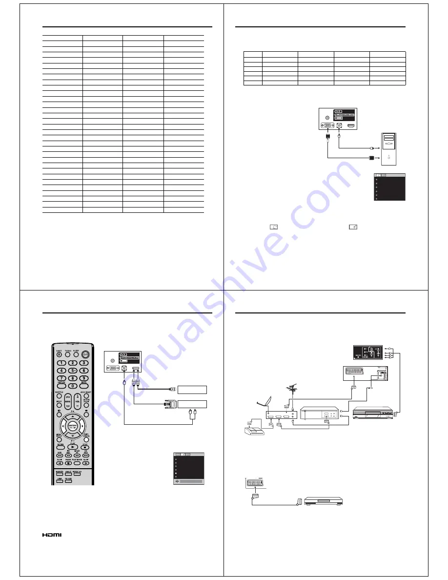
Language Code List

Enter the appropriate code number for the initial settings “Menu”, “Subtitle” and/or “Audio” (see pages 36). 

Language Name

Code Language Name

Code Language Name

Code Language Name

Code

Abkhazian

1112 Fiji

1620 Lingala

2224 Singhalese

2919

Afar

1111 Finnish

1619 Lithuanian

2230 Slovak

2921

Afrikaans

1116 French 1628 Macedonian

2321 Slovenian

2922

Albanian

2927 Frisian 1635 Malagasy

2317 Somali

2925

Amharic

1123 Galician 1722 Malay

2329 Spanish

1529

Arabic

1128 Georgian 2111 Malayalam

2322 Sundanese

2931

Armenian

1835 German

1415 Maltese

2330 Swahili

2933

Assamese

1129 Greek

1522 Maori

2319 Swedish

2932

Aymara

1135 Greenlandic 2122 Marathi

2328 Tagalog

3022

Azerbaijani

1136 Guarani 1724 Moldavian

2325 Tajik

3017

Bashkir

1211 Gujarati

1731 Mongolian

2324 Tamil

3011

Basque

1531 Hausa

1811 Nauru

2411 Tatar

3030

Bengali; Bangla

1224 Hebrew

1933 Nepali

2415 Telugu

3015

Bhutani

1436 Hindi

1819 Norwegian

2425 Thai

3018

Bihari

1218 Hungarian

1831 Oriya

2528 Tibetan

1225

Breton

1228 Icelandic

1929 Panjabi

2611 Tigrinya

3019

Bulgarian

1217 Indonesian

1924 Pashto, Pushto

2629 Tonga

3025

Burmese

2335 Interlingua

1911 Persian

1611 Turkish

3028

Byelorussian

1215 Irish 1711 Polish

2622 Turkmen

3021

Cambodian 2123 Italian

1930 Portuguese

2630 Twi

3033

Catalan

1311 Japanese 2011 Quechua

2731 Ukrainian

3121

Chinese

3618 Javanese

2033 Rhaeto-Romance

2823 Urdu

3128

Corsican

1325 Kannada 2124 Romanian

2825 Uzbek

3136

Croatian

1828 Kashmiri 2129 Russian

2831 Vietnamese

3219

Czech

1329 Kazakh 2121 Samoan

2923 Volapük

3225

Danish

1411 Kirghiz

2135 Sanskrit

2911 Welsh

1335

Dutch

2422 Korean 2125 Scots 

Gaelic 

1714 Wolof

3325

English

1524 Kurdish 2131 Serbian

2928 Xhosa

3418

Esperanto

1525 Laothian

2225 Serbo-Croatian

2918 Yiddish

2019

Estonian

1530 Latin

2211 Shona

2924 Yoruba

3525

Faroese

1625 Latvian, Lettish

2232 Sindhi

2914 Zulu

3631

51K0201A_ENG.indd   40

9/12/08   4:55:24 PM

41

PC connection

As PCs are sometimes supplied with a ‘conventional’ CRT monitor, you may need to adjust the display 
settings of your PC’s graphics card, otherwise the pictures may not appear correctly. Switch on your PC (still 
with your original monitor) - select ‘1360 x 768’ for the screen resolution, and select 60 Hz for the on-screen 
refresh rate. Switch off your PC, then connect it to your LCD TV while both items are still switched off.

Use a PC-VGA cable (not supplied) to connect the LCD-Monitor 
to your PC. Make the connections carefully so as not to break or 
bend the contacts inside the plug.

Select PC input 

Switch on the LCD-TV.
Select the PC input mode (see page 11).

Note:

If there is no video signal from the 
computer when the unit is in PC 
mode, “NO SIGNAL” will appear on 
the TV screen.
Digital PC connection via HDMI input 
is not supported.
If you try to connect your PC digitally 
anyway, the TV-operation might 
freeze. TV will stop to respond 
properly on usercommands. 

Countermeasure:

 Switch-off 

your TV and disconnect from the 
220~240V power-supply.
Disconnect the digital PC connection.
Now you may retry operating your TV.
If a digital PC connection does show 
a picture, proper working is not 
guaranteed. Digital PC connection is 
not granted for this TV.

Description about the each setting option:

PICTURE Menu 
BRIGHTNESS and CONTRAST:

 You can adjust 

these according to your personal preferences.

HOR POSITION and VER POSITION:

 to adjust the 

horizontal and vertical placing of the image.

PHASE and CLOCK:

 eliminates the horizontal 

(PHASE) and vertical (CLOCK) interfering lines.

RED/GREEN/BLUE:

 influences the colour balance.

BACKLIGHT:

 Press 

ϵ

 or 

϶

 to adjust the level you 

require.

WXGA INPUT:

 When you input an WXGA signal, 

set this option to “ON”.

RESET:

 Press

 ENTER

 to reset BRIGHTNESS, 

CONTRAST, RED, GREEN, BLUE and BACKLIGHT 
to the factory preset values.

AUDIO Menu 
BASS/TREBLE/BALANCE:

 Tone setting menu.

RESET:

 Press 

ENTER

 to reset BASS, TREBLE and 

BALANCE to the factory preset values. 

Example:

 Adjust the contrast.

1

During PC mode press 

MENU

.

The Menu will appear on the screen.

BRIGHTNESS

25

CONTRAST

40

HOR POSITION

0

VER POSITION

PHASE

25

CLOCK

0

0

2

Select CONTRAST, then press 

ENTER

. Press 

ϵ

 or 

϶

 to 

adjust CONTRAST.

3

Press 

EXIT

 to return to the normal screen.

VGA cable

(not supplied)

Audio cable

(not supplied)

PC

TV (Back side view)

to PC 
AUDIO 
input

Monitor Display modes

MODE

Resolution

V. Frequency

H. Frequency

Pixel Clock Frequency

VGA

640 x 480

60.000Hz 

31.500kHz

25.200MHz

SVGA

800 x 600

60.317Hz 

37.879kHz

40.000MHz

XGA

1024 x 768 

60.004Hz

48.363kHz

65.000MHz

WXGA

1280 x 720

59.870Hz

47.776kHz

79.500MHz

WXGA

1280 x 768

59.939Hz

44.955kHz

74.175MHz

WXGA

1360 x 768

60.015Hz

47.712kHz

85.5000MHz

(according to Graphic card)

51K0201A_ENG.indd   41

9/12/08   4:55:25 PM

42

The HDMI input receives digital audio and uncompressed video from a HDMI equipped device or 
uncompressed digital video from a DVI equipped device.
When you connect to a DVI device with a HDMI-to-DVI adapter cable, it only transfers the video signal, so it 
is necessary to use separate analogue leads to transfer the audio signals.
Select the HDMI input mode (see page11).

Connecting an HDMI


or a DVI device to the HDMI input

Note:

This set is classed as “HD-Ready”. 
This means that it is capable of 
displaying HD (High Definition) 
signals when connected to a suitable 
HD source, such as an HD receiver 
or DVD player that has HD capability, 
via HDMI, DVI, or Component Video 
connections.
Some devices may not operate 
properly with the TV. 

HDMI, the HDMI logo and High-
Definition Multimedia Interface are 
trademarks or registered trademarks of 
HDMI Licensing LLC.

Selecting the HDMI audio input source

You must choose the appropriate HDMI audio input setting for 
each connection, depending on whether the source is equipped 
with a DVI or HDMI socket.

1

Select HDMI AUDIO then press 

ENTER

.

Press 

ϵ

 or 

϶

 to select HDMI or DVI.

NICAM


AUTO

BASS 25

TREBLE 25

BALANCE 0

HDMI AUDIO


HDMI

RESET


HDMI

2

Press 

EXIT

 to return to the normal screen.


Note:

Follow the user’s manual that came with the HDMI-system, 
which you try to connect to this TV.
If there is no picture available via HDMI-connection, do 
connect via SCART-cable first. Use the HDMI-system’s 
remote-control to call the HDMI-system’s setup-menu onto 
the screen.
Follow the HDMI-system’s manual, to set its video-output to 
HDMI.
When successfully set to HDMI, select this TV’s HDMI-input, 
as described in here on page 11 (Select Video Input).

DVI device

HDMI device

To DVI 

output

Audio cable 

(not supplied)

HDMI - to - DVI adapter cable 

(HDMI type A connector) (not supplied)

HDMI cable (type A connector)

(not supplied)

To HDMI output

TV 

(Back side view)

To PC AUDIO 
input

or

51K0201A_ENG.indd   42

9/12/08   4:55:26 PM

43

ANT

AV1

AV

2

Decoder

(All 

i

llustrate

d

 SCART cables an

d

 antenna cables are not suppl

i

e

d

)

Satellite antenna

DVD player

Satellite 
receiver

Video recorder

Antenna 

 TV (Back side view)

 TV (Back side view)

D

EC

VCR

TV

R

Connection to other equipment

1. Connecting other units to your TV

Caution. Before connecting:

     •  Make sure to disconnect the appliance from the power  
    supply in order to avoid any potential damage from  
  occurring.
  •  Make sure to establish the required connection.
  •  Make sure that connections are properly and correctly  
    attached before connecting the appliances to the power  
  supply.

Connect with Satellite receiver as shown below.
Select the TV-Program at the satellite receiver. 
To do this, use the remote control of the satellite 
receiver. You cannot store the same station once again 
additionally in LCD-Monitor which already stored in 
satellite receiver.

2. Connecting a DVD player

Note:

S-Video signals can be played back through the AV2 input (see page 45).

To ensure optimum picture quality, 
select RGB for the DVD player’s output 
signal (see Owner’s manual of the DVD 
player). AV1 SCART is compatible with 
RGB signal. Select AV1 input mode to 
view (see page 11). 

DVD Player

(SCART cable, not suppl

i

e

d

)

 TV (Back side view)

51K0201A_ENG.indd   43

9/12/08   4:55:27 PM

Summary of Contents for 19DV550P

Page 1: ...The above models are classified as green products 1 as indicated by the underlined serial numbers This Service Manual describes replacement parts for the green products When repairing these green product s use the part s described in this manual and lead free solder 2 For 1 and 2 see the next page 2008 Toshiba Corporation 19DV551P ...

Page 2: ...parts is not only confined to manufacture The same green parts used in manufacture must also be used as replacement parts 2 LEAD FREE SOLDER This product is manufactured using lead free solder as a part of a movement within the consumer products industry at large to be environmentally responsible Lead free solder must be used in the servicing and repair of this product WARNING This product is manu...

Page 3: ...ER POWER OPERATION REMOCON SW POWER OPERATION REMOCON SCHEMATIC DIAGRAMS MPEG MICON DSP RF_AMP MEMORY MOTOR DRIVE AUDIO VIDEO 21PIN REGULATOR REGULATOR2 AV SWITCH SOUND AMP MUTE TUNER SCALER SUB MICON JACK INTERFACE_HDMI IC DVD_INTERFACE AV_SWITCH PANER_INTERFACE POWER BACKLIGHT INVERTER SOUND AMP JACK OUT SW INTERCONNECTION DIAGRAM WAVEFORMS MECHANICAL EXPLODED VIEW DVD DECK EXPLODED VIEW MECHANI...

Page 4: ...RDOUS RADIATION EXPOSURE IF DIRECTED BE SURE TO OPER ATE THE PLAYER CORRECTLY AS INSTRUCTED THE FOLLOWING CAUTION LABEL IS LOCATED ON THE REAR PANEL OF THE UNIT WHEN THIS UNIT IS PLUGGED INTO THE WALL OUTLET DO NOT PLACE YOUR EYES CLOSE TO THE OPENINGS TO LOOK INTO THE INSIDE OF THIS UNIT USE OF CONTROLS OR ADJUSTMENTS OR PERFORMANCE OF PROCEDURES OTHER THAN THOSE SPECIFIED HEREIN MAY RESULT IN HA...

Page 5: ...ots This is not a sign of a malfunction Please take note EXCLUSION CLAUSE Toshiba shall under no circumstances be liable for loss and or damage to the product caused by i fire ii earthquake iii accidental damage iv intentional misuse of the product v use of the product in improper conditions vi loss and or damage caused to the product whilst in the possession of a third party vii any damage or los...

Page 6: ...according to its own instructions Preparation Press Power on the unit or press On Standby on the remote control 1 AUTO INSTALLATION menu will appear Press ϳ or ϴ to select LANGUAGE then press ENTER Press ϵ or to select desired language Then press ENTER LANGUAGE COUNTRY AUTO TUNING AUTO INSTALLATION ENGLISH EXIT END MENU RETURN GERMANY ENGLISH 2 Press ϳ or ϴ to select COUNTRY then press ENTER Press...

Page 7: ...eration Note If the built in tuner does not receive anything e g if no antenna is connected during TV operation then the TV unit will change to standby after approx 15 minutes Channel selection With the numbered buttons Example No 2 Press 0 and within 2 seconds press 2 No 29 Press 2 and within 2 seconds press 9 Press P or to change up or down a channel This takes approx 2 seconds If the auto searc...

Page 8: ...factory set MOVIE Movie like picture setting factory set MEMORY Your personal preferences BRIGHTNESS CONTRAST COLOUR TINT NTSC SHARPNESS You can adjust the picture to your preference The TINT NTSC option can be selected if an NTSC 3 58MHz or NTSC 4 43MHz signal is input through one of the AV sockets and NTSC or AUTO has been selected for the AV COLOUR option COLOUR TEMPERATURE Bluish COOL Neutral ...

Page 9: ... at this time This does not indicate a problem with the unit You can play discs at various speeds Playing in fast reverse or fast forward directions DVD VCD Audio CD Press or during playback Fast reverse playback Fast forward playback Each time you press or the playback speed changes To resume normal playback Press PLAY Note The unit mutes sound during reverse and forward scan of DVD VCD Audio CD ...

Page 10: ...yback The current angle will appear 1 2 2 Press ANGLE repeatedly until the desired angle is selected Note Depending on the DVD you may not be able to change the angles even if multi angles are recorded on the DVD Title selection DVD Two or more titles are recorded on some discs If the title menu is recorded on the disc you can select the desired title 1 Press TOP MENU during playback Title menu ap...

Page 11: ...elect Files at right column in the file browser Select Files is not applicable to Audio CD Press ENTER then press ϳ or ϴ to select file type from the list Music Picture or Movie Press ENTER to add remove check mark Checked file type will be displayed in the file browser Press RETURN to save the setting 1 2 3 4 Note MP3 file on the Kodak Picture CD is not recognized on this unit During MP3 JPEG Pla...

Page 12: ...4 Press ϵ to return to the left column then press ϳ ϴ to select the Program Playback and press ENTER The programs you selected will start to playback in order To resume normal playback select Mode Off in step 2 To change the program Select Mode to Program as step 2 press ϳ ϴ ϵ to select the track number you want to change then press CANCEL Press Number buttons 0 9 to overwrite the new track number...

Page 13: ...lby Digital is played back The level of Night Mode may differ depending on DVD video disc Digital Out You can select the digital output sound format corresponding to your system connection Off There is no sound output from DIGITAL AUDIO OUT jack PCM Change Dolby Digital to PCM for the output Select when connected to a 2 channel digital stereo amplifier Bitstream Disc audio bitstream data will be o...

Page 14: ...set BASS TREBLE and BALANCE to the factory preset values Example Adjust the contrast 1 During PC mode press MENU The Menu will appear on the screen BRIGHTNESS 25 CONTRAST 40 HOR POSITION 0 VER POSITION PHASE 25 CLOCK 0 0 2 Select CONTRAST then press ENTER Press ϵ or to adjust CONTRAST 3 Press EXIT to return to the normal screen VGA cable not supplied Audio cable not supplied PC TV Back side view t...

Page 15: ...R TV Outputs the last channel position selected MONITOR The picture displayed on TV screen AV1 OUTPUT AV COLOUR TV AUTO RESET TV SETTING TV 3 Press EXIT to return to the normal screen AV colour adjustment The AV Colour setting only applies when viewing devices connected to the AV inputs 1 In select AV COLOUR then press ENTER 2 Press ϵ or to select AUTO AV1 OUTPUT AV COLOUR AUTO AUTO RESET TV SETTI...

Page 16: ...cm 8cm CD 12cm 8cm Output Audio RCA 12 0 dBm 1 k ǣ Digital Audio 0 5Vp p 75 ǣ Pickup CD Wavelength 775 805 nm Maximum output power 0 5 mW DVD Wavelength 640 660 nm Maximum output power 1 0 mW GENERAL Power Source AC 220 240V 50Hz Power Consumption Operation approx 55W at 230V 50Hz Standby approx 1W at 230V 50Hz Weight 5 1 kg Dimensions 47 2 W x40 1 H x20 7 D cm Surrounding temperature Operation 5 ...

Page 17: ...original positions or whether there are the portions which are deteriorated around the serviced places serviced or not Check the insulation between the antenna terminal or external metal and the AC cord plug blades And be sure the safety of that INSULATION CHECK PROCEDURE 1 2 3 4 Unplug the plug from the AC outlet Remove the antenna terminal on TV and turn on the TV Insulation resistance between t...

Page 18: ... position after the connection of Pick Up PCB and DVD MT PCB connector NOTE Before your operation please read REPARATION OF SERVICING Use the Lead Free solder Manual soldering conditions Soldering temperature 320 20o C Soldering time Within 3 seconds Soldering combination Sn 3 0Ag 0 5Cu When Soldering Removing of solder use the draw in equipment over the Pick Up Unit to keep the Flux smoke away fr...

Page 19: ...the 7 key on the remote control unit Hold both keys for more than 2 seconds The On Screen Display message PASSWORD CLEAR will appear The 4 digit password has now been cleared 1 2 3 4 5 6 7 8 PARENTAL CONTROL RATING LEVEL 4 DIGIT PASSWORD CANCELLATION The disk cannot be taken out by setting the Tray Lock please follow the steps below Turn Unit ON Set the DVD to the Stop Mode Press it in order of SE...

Page 20: ...ZOOM 45 BA 40 25 HOLD 40 BF 53 26 TEXT TV 45 BA 79 27 CH PAGE 40 BF 3E 28 LEFT 44 BB 51 29 ENTER CHANNEL LIST 40 BF 3D 30 RIGHT 44 BB 4D 31 CH PAGE 40 BF 3F 32 MENU SETUP 40 BF 0E 33 EXIT CANCEL 44 BB EF 34 RETURN 44 BB 5D 35 PLAY 44 BB 15 36 STOP 44 BB 14 37 SKIP 45 BA 23 38 REVEAL SEARCH 45 BA 19 39 SUB PAGE SEARCH 45 BA 13 40 F T B SKIP 45 BA 24 41 RED SLOW 45 BA 0E 42 GREEN PAUSE 45 BA 15 43 Y...

Page 21: ...FT RIGHT button on the remote control set the mode to desired setting The Hotel mode has now been set up Note 1 Note 2 Note 3 Note 4 Even if setting it to No Respond the remote control key operation in Hotel mode and service mode function are effective Even if setting it to No Respond the service mode function are effective If setting it to OFF it start up in same input source when you turn off th...

Page 22: ... System Tuner and System 1Tuner Analog Receive CH Destination UK I R CCIR Hyper France CATV CH Coverage Analog IreE2 E4 X Z 2 S1 S10 E5 E12 S11 S41 E21 E69 Digital Intermediate Analog BG II DK L L SECAM VL Frequency Picture FP 38 9 38 9 38 9 33 9MHz Sound FS 33 4 32 9 32 4 40 4MHz FP FS 5 5 6 0 6 5 6 5MHz Digital Auto Tuning Method ALL Band Not C C I R CH Plan Preset CH Analog 99 Digital Stereo Du...

Page 23: ...Program On Timer Off Timer Program Wake Up Timer No Timer Back up at Power Off Mode more than Min Sec G 11 Remote Unit RC PT Control Glow in Dark Remocon No Remocon Format TOSHIBA Format TOSHIBA Custom Code 40 BF h 44 BB h 45 BA h 45 BC h Power Source Voltage D C 3V UM size x pcs UM 4 x 2 pcs Total Keys 49 Keys Keys Power Stand By Yes Display Status Yes Menu Setup Yes Digital Menu No Input Select ...

Page 24: ...ast installation Auto tuning Analog tuner Yes CH sort Yes ATS Yes Auto clock Analog tuner No Plug in start Yes Picture Setting TV Picture Preference Yes Brightness Contrast Color Yes Tint Yes Sharpness Yes DNR No Color Temperature Yes Blue Back Yes Backlight Control Yes Film Mode No Picture Setting PC BRIGHTNESS CONTRAST Yes HOR POSITION VER POSITION Yes PHASE CLOCK Yes AUTO ADJUST No RED GREEN BL...

Page 25: ...20 Yes 60Hz WXGA 1360x768 Yes 60Hz SXGA 1280x1024 No HDMI Input Yes VGA 640 480 Yes 60Hz 720 480i 4 3 Yes 60Hz 720 480i 16 9 Yes 60Hz 720 480p 4 3 Yes 60Hz 720 480p 16 9 Yes 60Hz 720 576i 4 3 Yes 50Hz 720 576i 16 9 Yes 50Hz 720 576p 4 3 Yes 50Hz 720 576p 16 9 Yes 50Hz 1280 720p Yes 50 60Hz 1920 1080i Yes 50 60Hz Component Input Yes 720 480i 4 3 Yes 60Hz 720 480i 16 9 Yes 60Hz 720 480p 4 3 Yes 60Hz...

Page 26: ...e Power Tact Yes System Select No Main Power SW No Channel Up Menu Up Play Yes Channel Down Menu Down Stop Yes Volume Up Menu Yes Volume Down Menu Yes Play No CH Alternative Eject Yes Skip Search No Skip Search No Stop No CH Alternative Input Select Enter Yes Menu Yes Indicator Power Stand by EPG Timer Yes GREEN RED On Timer No Terminals Side CI Card Slot No Rear Video Input 1 RCA x 1 AV2 Audio In...

Page 27: ... Origin No Gift Box Yes Material Double Full Color Dimensions W x D x H mm 558 x 565 x 181 W Color Photo Label No Description of Origin Yes Drop Test 6 Surfaces Height cm 80 Container Stuffing 880 Sets 40 container w Pallet Yes w Wrapping Yes G 18 Material Cabinet Cabinet Front PC ABS 94V0 NON HALOGEN Cabinet Rear PS 94V0 NON DECABROM PCB Non Halogen No Eyelet Yes G 19 Environment Environmental st...

Page 28: ...0 E5 E12 S11 S41 E21 E69 Digital Intermediate Analog BG II DK L L SECAM VL Frequency Picture FP 38 9 38 9 38 9 33 9MHz Sound FS 33 4 32 9 32 4 40 4MHz FP FS 5 5 6 0 6 5 6 5MHz Digital Auto Tuning Method ALL Band Not C C I R CH Plan Preset CH Analog 99 Digital Stereo Dual TV Sound Nicam A2 Dual Tuner Sound Muting Yes G 4 Signal Video Signal Input Level 1 V p p 75 ohm Output Level 1 V p p 75 ohm S N...

Page 29: ...l Glow in Dark Remocon No Remocon Format TOSHIBA Format TOSHIBA Custom Code 40 BF h 44 BB h 45 BA h 45 BC h Power Source Voltage D C 3V UM size x pcs UM 4 x 2 pcs Total Keys 49 Keys Keys Power Stand By Yes Display Status Yes Menu Setup Yes Digital Menu No Input Select Yes TV DVB T No Guide EPG No Picture Size Yes 1 Yes 2 Yes 3 Yes 4 Yes 5 Yes 6 Yes 7 Yes 8 Yes 9 Yes 0 Yes Sleep Yes Mute Yes Volume...

Page 30: ...sition No DNR Yes 3D Comb Filter Yes 3D Auto Set Up Fast installation Auto tuning Analog tuner Yes CH sort Yes ATS Yes Auto clock Analog tuner No Plug in start Yes Picture Setting TV Picture Preference Yes Brightness Contrast Color Yes Tint Yes Sharpness Yes DNR No Color Temperature Yes Blue Back Yes Backlight Control Yes Film Mode No Picture Setting PC BRIGHTNESS CONTRAST Yes HOR POSITION VER POS...

Page 31: ...cart2 AV in No AV out No S Video in No RGB in No PC Monitor Input Yes VGA 640x480 Yes 60Hz VGA 720x400 No WVGA 848x480 No SVGA 800x600 Yes 60Hz XGA 1024x768 Yes 60Hz WXGA 1280x768 Yes 60Hz WXGA 1280x720 Yes 60Hz WXGA 1360x768 Yes 60Hz SXGA 1280x1024 No HDMI Input Yes VGA 640 480 Yes 60Hz 720 480i 4 3 Yes 60Hz 720 480i 16 9 Yes 60Hz 720 480p 4 3 Yes 60Hz 720 480p 16 9 Yes 60Hz 720 576i 4 3 Yes 50Hz...

Page 32: ...t Diagram No Antenna Change Plug No Service Facility List No Important Safeguard No Dew AHC Caution Sheet No Quick Set up Sheet Yes My Movie stream Free DVD redemption voucher No Carbon Neutral Certificate No Battery Yes UM size x pcs UM 4 x 2 pcs OEM Brand No AC Adapter No AC Cord for AC Adapter No AC Cord Yes AV Cord 2Pin 1Pin No RF Cable Yes HDMI DVI Cable No Helpline Sheet No 300 ohm to 75 ohm...

Page 33: ...HDMI DVI In use No G 15 Set Size Approx W x D x H mm 472 x 207 x 401 w o Stand Handle Approx W x D x H mm 472 x 67 x 364 G 16 Weight Net Approx 5 1kg 11 2 lbs Net w o Stand Handle Approx 4 4kg 9 7 lbs Gross Approx 6 8kg 15 0 lbs G 17 Carton Master Carton No Content Sets Material Dimensions W x D x H mm x x Description of Origin No Gift Box Yes Material Double Full Color Dimensions W x D x H mm 558...

Page 34: ...lowing connectors CD7005 CD7006 and CD7204 Remove the LCD PANEL in the direction of arrow B Disconnect the following connector CP7601 Remove the Remocon PCB in the direction of arrow C 1 2 FRONT CABINET ASS Y LCD PANEL AND REMOCON PCB Refer to Fig 1 2 1 2 3 4 5 6 7 8 Front Cabinet Ass y A Fig 1 2 Remocon PCB LCD Panel B CP7601 C CAUTION Never lift the LCD Panel more than 90o the LCD Panel or the c...

Page 35: ... R Ass y CP5803 Plate Pcb CP6501 TUNER PCB 1 1 5 DVD DECK Refer to Fig 1 5 1 2 3 4 5 6 7 8 Short circuit the position shown in Fig 1 5 using a soldering iron If you remove the DVD Deck with no soldering the Laser may be damaged Remove the 5 screws 1 Remove the DVD Deck in the direction of arrow A Disconnect the following connectors CP2301 CP2302 and CP2303 Remove the 2 screws 2 Remove the Angle Mp...

Page 36: ...Hook Loader Ass y Bottom Side Check Lock Check Lock Fig 2 1 C Loader Ass y 80 5mm Check Hook Fig 2 1 D Loader Ass y Top Side Check Hook Check Hook Check Hook 2 2 Remove the Insulator F Remove the Insulator R Unlock the support 1 Remove the Gear Middle Remove the screw 2 Remove the Rack Feed Ass y Remove the screw 3 Remove the Switch PCB Ass y Remove the screw 4 Remove the Gear Feed Remove the 2 sc...

Page 37: ...ual soldering conditions Soldering temperature 320 20o C Soldering time Within 3 seconds Soldering combination Sn 3 0Ag 0 5Cu After the assembly of the Traverse Ass y hook the wire on the Traverse Ass y as shown Fig 2 2 E OK NG Fig 2 2 B Rack Feed Ass y Push Push When installing the FFC fold it correctly and install it as shown from Fig 2 3 A to Fig 2 3 B 2 3 FFC WIRE HANDLING 1 Do not make the fo...

Page 38: ...ne IC Heat the IC leads using a blower type IC desoldering machine Refer to Fig 3 2 2 Fig 3 2 NOTE Do not rotate or move the IC back and forth until IC can move back and forth easily after desoldering the leads completely When IC starts moving back and forth easily after desoldering completely pickup the corner of the IC using tweezers and remove the IC by moving with the IC desoldering machine Re...

Page 39: ... 8 4 Fig 3 8 Thin tip Soldering Iron NOTE When the IC leads are bent during soldering and or repairing do not repair the bending of leads If the bending of leads are repaired the pattern may be damaged So always be sure to replace the IC in this case Finally confirm the soldering status on four sides of the IC using a magnifying glass Confirm that no abnormality is found on the soldering position ...

Page 40: ... ON total hours are displayed on the screen Can be checked of the INITIAL DATA of MEMORY IC Refer to the WHEN REPLACING EEPROM MEMORY IC VOL DOWN Minimum 6 2 sec VOL DOWN Minimum 9 2 sec TV mode ALL mode Display of the Adjustment MENU on the screen Refer to the ELECTRICAL ADJUSTMENT On Screen Display Adjustment 5 2 sec DVD Write mode Refer to the RE WRITE FOR DVD FIRMWARE VOL DOWN Minimum DVD mode...

Page 41: ...ppear Unplug the AC cord then plug it in After the write set to the initializing of shipping Turn on the power and set the DVD mode Press both VOL DOWN button on the set and Channel button 4 on the remote control for more than 2 seconds The INITIALIZE 5 COMPLETE will appear on the screen Then unplug the AC cord and plug it in CHECK FOR THE FIRMWARE VERSION Turn on the power and set the DVD mode Pr...

Page 42: ...V mode Set the VOLUME to minimum Press both VOL DOWN button on the set and Channel button 2 on the remote control for more than 2 seconds After the confirmation of each check sum turn off the power CONFIRMATION OF CHECK SUM POWER ON TOTAL HOURS AND MICON VERSION Initial total of MEMORY IC POWER ON total hours and MICON VERSIONcan be checked on the screen Total hours are displayed in 16 system of n...

Page 43: ... MAX V POSI MIN BACKLIGHT CENTER BACKLIGHT MAX BACKLIGHT MIN BRIGHT CENTER BRIGHT MAX BRIGHT MIN TINT CENTER CONTRAST CENTER CONTRAST MAX CONTRAST MIN CONTRAST 50 COLOR CENTER COLOR MAX COLOR MIN TEXT H POSI TEXT V POSI FLICKER ADJ Fig 1 2 2 BASIC ADJUSTMENTS 2 1 WHITE BALANCE 1 2 3 4 5 6 7 8 Place the set in Aging Test for more than 15 minutes Receive the gray scale pattern from the Pattern Gener...

Page 44: ...s the channel button 35 on the remote control to select CONTRAST MAX Press the LEFT RIGHT button on the remote control until the contrast step No becomes 51 Check if the picture is normal Receive the monoscope pattern VIDEO Input Press the INPUT button on the remote control to set to the AV1 CVBS mode Using the remote control set the brightness and contast to normal position Then perform the above...

Page 45: ... 26 26 24 x x x x 26 54 x x x x x x x 10 40 9 8 x x x x x x 26 V POSI 50Hz FULL 26 26 26 24 x x x x 26 54 x x x x x x x 10 40 x x x x x x x x 26 V POSI 50Hz Cinema 60 60 60 58 x x x x 61 124 x x x x x x x 47 110 x x x x x x x x 60 V POSI 50Hz 14 9 43 43 43 38 x x x x 44 91 x x x x x x x 32 79 x x x x x x x x 43 V POSI 60Hz 4 3 16 9 18 18 18 16 18 42 9 8 x x x x 8 26 30 9 8 x x x x x x x x x x 20 V...

Page 46: ...80 80 80 80 80 80 80 80 80 80 80 33 TINT CENTER 0 0 0 0 0 0 0 0 4 0 0 4 0 0 0 0 0 0 0 0 0 0 0 34 CONTRAST CENTER 35 CONTRAST MAX 36 CONTRAST MIN 18 18 18 18 18 18 18 18 18 18 18 18 18 18 18 18 18 18 18 18 18 18 18 37 CONTRAST 50 38 COLOR CENTER 40 40 40 40 40 40 40 40 44 40 40 44 40 40 40 40 40 40 40 40 40 40 40 39 COLOR MAX 63 63 63 63 63 63 63 63 63 63 63 63 63 63 63 63 63 63 63 63 63 63 63 40 C...

Page 47: ...CD2001 CD2301 DVD MT PCB CP2301 CP2303 CP2302 CP8501 CP8502 MAIN PCB POWER PCB J501 J301 CD301 CP8101 SPEAKER CP501 J4206 CP4300 CP3801 CP7200 OPERATION PCB CP2201 CD7005 CD6501 CD7204 CP5802 TUNER PCB CP5803 TU5801 AC IN CD501 CD7006 CP6501 CD4301 CD4302 J8101 J8104 REMOCON PCB OS7601 CP7601 19DV550P 19DV551P ...

Page 48: ... LCD SECTION POWER DOES NOT TURN ON Is F501 broken Is there voltage at pin 6 of IC501 21V Is R510 broken Change F501 Check IC501 and peripheral circuit Change MAIN PCB No Yes Change R510 No No Yes Yes E 1 19DV550P 19DV551P ...

Page 49: ...onnected Is there signal at pins 1 and 4 of CD301 Is there signal at pins 2 and 4 of IC301 Connect CD301 Change SP301 and SP302 Change TU5801 Check IC301 and peripheral circuit Yes Yes Yes No No No Is there signal at pin14 of TU5801 Check IC803 and peripheral circuit Yes No E 2 19DV550P 19DV551P ...

Page 50: ...backlight shine Is CD7204 connected Connected CD7204 Is CD7005 CD7006 connected Connected CD7005 CD7006 Yes No No No No Yes Yes Yes Yes No Check Q3810 and peripheral circuit Is there voltage at pins 1 2 and 16 of CP7200 5V Is the signal pin 16 and18 of IC7001 Is the voltage at pin 20 of IC7001 12V Yes Yes Check IC7001 and peripheral circuit Check F7001 No No E 3 19DV550P 19DV551P ...

Page 51: ...TROUBLESHOOTING GUIDE Is setting of color normal Is the color signal received Adjust the color Receive the color signal Change MAIN PCB THE COLOR DOES NOT APPEAR Yes No Yes No E 4 19DV550P 19DV551P ...

Page 52: ...s display logo picture Is there signal at pins 149 and 151 of IC4001 Does IC4001 gets P CON 3 3V and P CON 1 8V Check P CON 3 3V and P CON 1 8V line Check pins 8 and 10 of CP8501 and peripheral circuit Yes No Yes No Change IC4001 Check the disc Yes No E 5 19DV550P 19DV551P ...

Page 53: ... Is remote key set effectively Yes No No Yes Yes DISC DOES NOT EJECT Is there signal at pins 4 and 5 of CP2302 Check IC4001 and peripheral circuit No Is there signal at pins 1 and 2 of CP2302 No Yes Change IC4001 Yes Check pins 138 and 139 of IC4001 and peripheral circuit Change IC2301 E 6 19DV550P 19DV551P ...

Page 54: ...t with CP2301 correctly Yes No No Yes DOES NOT PLAY DVD Does this display reading mark No Does disc rotate No Yes Change IC4001 Yes Change DVD DECK Connect CD2301 Change DVD DECK Is the voltage between JG017 and JG018 less than 3 3V Yes No Change IC4001 E 7 19DV550P 19DV551P ...

Page 55: ...t with CP2301 correctly Yes No No Yes DOES NOT PLAY CD Does this display reading mark No Does disc rotate No Yes Change IC4001 Yes Change DVD DECK Connect CD2301 Change DVD DECK Is the voltage between JG019 and JG018 less than 3 3V Yes No Change IC4001 E 8 19DV550P 19DV551P ...

Page 56: ...01 and peripheral circuit Yes NO SOUND DVD CD ANALOG AUDIO No Change MAIN PCB Change IC4001 Connected CD8501 Is there signal at pin1 of CP8501 Is there signal at pin122 of IC4001 Check line circuit IC4001 to CP8501 Yes NO SOUND DVD CD DIGITAL AUDIO No Change IC4001 Yes No No Yes No Yes Change MAIN PCB Does CD8501 connected E 9 19DV550P 19DV551P ...

Page 57: ...04 204 204 204 202 202 202 104 PCB130 DVD MT PCB ASS Y 203 203 206 206 208 208 105 116 208 208 114 203 123 208 208 117 PCB290 TUNER PCB ASS Y 208 110 208 122 208 103A 103C 103B 103D 103 210 208 101A 101D 101B 101C 101E 101F 101F 101G 101G 201 101 101F 101H 101I 101H 101I 208 208 208 121 115 212 108 207 207 115 213 214 211 118 PCB270 OPERATION PCB ASS Y 102C 102B 102A 102D 102D 208 102 107 109 112 ...

Page 58: ... 204 204 204 202 202 202 104 PCB130 DVD MT PCB ASS Y 203 203 206 206 208 208 105 116 208 208 114 203 123 208 208 117 PCB290 TUNER PCB ASS Y 208 110 208 122 208 103A 103C 103B 103D 103 208 208 101A 101D 101B 101C 101E 101F 101F 101G 101G 201 101 101F 101H 101I 101H 101I 208 208 208 121 115 212 108 207 207 115 213 210 211 118 PCB270 OPERATION PCB ASS Y 102C 102B 102A 102D 102D 208 102 107 109 112 11...

Page 59: ...MECHANICAL EXPLODED VIEW PACKING DIAGRAM 130 124 133 134 135 CD501 CD3805 TM101 131 127 127 129 125 126 126 128 J1 5 19DV550P 132 128 128 ...

Page 60: ...MECHANICAL EXPLODED VIEW PACKING DIAGRAM 130 133 134 135 136 CD501 CD3805 TM101 131 127 127 129 125 126 126 128 J1 6 19DV551P 132 128 128 ...

Page 61: ...ach position NOTE Do not replace the parts Because minute adjustments are needed if this condition is disassembled further more If the repair is needed replace the DVD MECHA ASS Y PCB640 SW PCB ASS Y 701 702 702 607 604 CD2001 603 M2602 606 602 704 703 605 SW2 705 CD2301 AA 703 703 605 601 608 608 600 CLASS GREASE MARK AA 19DV550P 19DV551P ...

Page 62: ...134 FELT SHEET 40 60 T0 5 114 AE008287 726000A139 SHEET CAUTION 115 AE009784 744WUA0038 SPRING EARTH 3 116 AE009627 899RFPC25V HOLDER CORD 117 AE009858 753WUA0101 SPRING EARTH 1 118 AE009600 761WPAA180 HOLDER REMOCON 119 AE009601 761WPAA184 HOLDER SPEAKER L 120 AE009602 761WPAA187 HOLDER SPEAKER R 121 AE009629 761WPA0515 HOLDER PCB 122 AE009788 761WPA0523 PLATE PCB 123 AE009841 752WSA0723 SPRING E...

Page 63: ...96 800WQ00134 FELT SHEET 40 60 T0 5 114 AE008287 726000A139 SHEET CAUTION 115 AE009784 744WUA0038 SPRING EARTH 3 116 AE009627 899RFPC25V HOLDER CORD 117 AE009858 753WUA0101 SPRING EARTH 1 118 AE009600 761WPAA180 HOLDER REMOCON 119 AE009601 761WPAA184 HOLDER SPEAKER L 120 AE009602 761WPAA187 HOLDER SPEAKER R 121 AE009629 761WPA0515 HOLDER PCB 122 AE009788 761WPA0523 PLATE PCB 123 AE009841 752WSA072...

Page 64: ...P100116A GEAR FEED 608 AE016078 800WFAA008 CUSHION C 701 AE005817 92P700007A SCREW GEAR FEED 702 AE003554 814011723U SCREW PAN M1 7 2 3 P3 CH 703 AE003555 816112080U SEMS TAP TITE P PAN W10 2 8 CH 704 AE005006 813381750U SCREW T TITE B CAMERA PAN M1 7 5 0 P3 CH 705 AE003557 811022080U SCREW TAP TITE P BIND 2 8 CH CD2001 AE009434 12C14O1602 CORD JUMPER FFC05241600408T1 A04 CD2301 AE003558 122H06210...

Page 65: ...P100116A GEAR FEED 608 AE016078 800WFAA008 CUSHION C 701 AE005817 92P700007A SCREW GEAR FEED 702 AE003554 814011723U SCREW PAN M1 7 2 3 P3 CH 703 AE003555 816112080U SEMS TAP TITE P PAN W10 2 8 CH 704 AE005006 813381750U SCREW T TITE B CAMERA PAN M1 7 5 0 P3 CH 705 AE003557 811022080U SCREW TAP TITE P BIND 2 8 CH CD2001 AE009434 12C14O1602 CORD JUMPER FFC05241600408T1 A04 CD2301 AE003558 122H06210...

Page 66: ...ER 1H3 E D512 AE002133 D2BXARS010 DIODE SILICON SARS01 V1 D514 AE011472 D28T21DQN9 DIODE SCHOTTKY 21DQ09N TA2B1 D515 AE009803 D28A10A080 DIODE SCHOTTKY BARRIER FCHS10A08 D516 AE008319 D4AT01H3E0 DIODE RECTIFIER 1H3 E D517 AE011502 D97U01601B DIODE ZENER MTZJ16B T 77 D518 AE011441 D2WTRM11C0 DIODE SILICON RM11C EIC D523 AE009803 D28A10A080 DIODE SCHOTTKY BARRIER FCHS10A08 D804 AE009498 DGJRT54WS0 D...

Page 67: ...M 2K 12C S 24CS02AFJ TB GE IC3801 AE007825 I07F0C0WF0 1A REGULATOR BA00BC0WFP E2 IC3806 AE009719 I5HJ950UC0 REGULATOR VO 5 0V IO 800MA S 1170B50UC OUJTFG IC4001 AE009720 ICQK06966A VADDIS9 MPEG MICON DSP RF AMP ZR36966ELCG D G IC4005 AE008324 IF9J0164AG 1M 16 4BANK 64M 143MHZ SDRAM M12L64164A 7TG IC4007 AE016515 S51Z01AF01 MEMORY DATA NOR FLASH 16M B00T SST39VF1601 70 4C EKE IC4302 AE011796 I0UF01...

Page 68: ...E009519 02D1000119 COIL CHOKE EXC28CG900U L3602 AE009519 02D1000119 COIL CHOKE EXC28CG900U L4204 AE013298 0216SD220J COIL 22 UH L4205 AE013298 0216SD220J COIL 22 UH L4206 AE013298 0216SD220J COIL 22 UH L4207 AE013298 0216SD220J COIL 22 UH L7001 AE013322 02167E100K COIL 10 UH L8501 AE008874 0216SD2R2J COIL 2 2 UH L8502 AE006570 0216SD1R0J COIL 1 UH T501 AE009724 0481240038 TRANSFORMER SWITCHING 812...

Page 69: ...06 AE008552 024NC51021 CORE BEADS EBMS160808A102_RDC45 B4008 AE008552 024NC51021 CORE BEADS EBMS160808A102_RDC45 B4010 AE008552 024NC51021 CORE BEADS EBMS160808A102_RDC45 B4015 AE008552 024NC51021 CORE BEADS EBMS160808A102_RDC45 B4016 AE008552 024NC51021 CORE BEADS EBMS160808A102_RDC45 B4202 AE008395 024HC56005 CORE BEADS FCM1608CF 600T06 B4203 AE008879 024HC56013 CORE BEADS FCM1608KF 601T02 B4204...

Page 70: ...CRA108330JV NR3605 AE016524 11074330M7 R NETWORK CRA108330JV NR3606 AE016524 11074330M7 R NETWORK CRA108330JV NR7200 AE009744 11074000M7 R NETWORK CRA108000JV NR7201 AE009744 11074000M7 R NETWORK CRA108000JV NR7202 AE009744 11074000M7 R NETWORK CRA108000JV NR7203 AE009744 11074000M7 R NETWORK CRA108000JV NR7204 AE009557 11074470M7 R NETWORK CRA108470JV NR7205 AE009557 11074470M7 R NETWORK CRA10847...

Page 71: ...ER 1H3 E D512 AE002133 D2BXARS010 DIODE SILICON SARS01 V1 D514 AE011472 D28T21DQN9 DIODE SCHOTTKY 21DQ09N TA2B1 D515 AE009803 D28A10A080 DIODE SCHOTTKY BARRIER FCHS10A08 D516 AE008319 D4AT01H3E0 DIODE RECTIFIER 1H3 E D517 AE011502 D97U01601B DIODE ZENER MTZJ16B T 77 D518 AE011441 D2WTRM11C0 DIODE SILICON RM11C EIC D523 AE009803 D28A10A080 DIODE SCHOTTKY BARRIER FCHS10A08 D804 AE009498 DGJRT54WS0 D...

Page 72: ...M 2K 12C S 24CS02AFJ TB GE IC3801 AE007825 I07F0C0WF0 1A REGULATOR BA00BC0WFP E2 IC3806 AE009719 I5HJ950UC0 REGULATOR VO 5 0V IO 800MA S 1170B50UC OUJTFG IC4001 AE009720 ICQK06966A VADDIS9 MPEG MICON DSP RF AMP ZR36966ELCG D G IC4005 AE008324 IF9J0164AG 1M 16 4BANK 64M 143MHZ SDRAM M12L64164A 7TG IC4007 AE016515 S51Z01AF01 MEMORY DATA NOR FLASH 16M B00T SST39VF1601 70 4C EKE IC4302 AE011796 I0UF01...

Page 73: ...E009519 02D1000119 COIL CHOKE EXC28CG900U L3602 AE009519 02D1000119 COIL CHOKE EXC28CG900U L4204 AE013298 0216SD220J COIL 22 UH L4205 AE013298 0216SD220J COIL 22 UH L4206 AE013298 0216SD220J COIL 22 UH L4207 AE013298 0216SD220J COIL 22 UH L7001 AE013322 02167E100K COIL 10 UH L8501 AE008874 0216SD2R2J COIL 2 2 UH L8502 AE006570 0216SD1R0J COIL 1 UH T501 AE009724 0481240038 TRANSFORMER SWITCHING 812...

Page 74: ...06 AE008552 024NC51021 CORE BEADS EBMS160808A102_RDC45 B4008 AE008552 024NC51021 CORE BEADS EBMS160808A102_RDC45 B4010 AE008552 024NC51021 CORE BEADS EBMS160808A102_RDC45 B4015 AE008552 024NC51021 CORE BEADS EBMS160808A102_RDC45 B4016 AE008552 024NC51021 CORE BEADS EBMS160808A102_RDC45 B4202 AE008395 024HC56005 CORE BEADS FCM1608CF 600T06 B4203 AE008879 024HC56013 CORE BEADS FCM1608KF 601T02 B4204...

Page 75: ...RA108330JV NR3605 AE016524 11074330M7 R NETWORK CRA108330JV NR3606 AE016524 11074330M7 R NETWORK CRA108330JV NR7200 AE009744 11074000M7 R NETWORK CRA108000JV NR7201 AE009744 11074000M7 R NETWORK CRA108000JV NR7202 AE009744 11074000M7 R NETWORK CRA108000JV NR7203 AE009744 11074000M7 R NETWORK CRA108000JV NR7204 AE009557 11074470M7 R NETWORK CRA108470JV NR7205 AE009557 11074470M7 R NETWORK CRA108470...

Page 76: ...TOSHIBA CORPORATION 1 1 SHIBAURA 1 CHOME MINATO KU TOKYO 105 8001 JAPAN ...

Reviews: