background image

Storage

Cleaning and Storage

1. Disengage the power take off (PTO), set the

parking brake, and turn the ignition key to Off.
Remove the key.

2. Remove grass clippings, dirt, and grime from

the external parts of the entire machine,
especially the engine and hydraulic system.
Clean dirt and chaff from the outside of the
engine cylinder head fins and blower housing.

Important:

You can wash the machine

with mild detergent and water. Do
not pressure wash the machine. Avoid
excessive use of water, especially near the
control panel, engine, hydraulic pumps,
and motors.

3. Check the brake; refer to Servicing the Brake

in Brake Maintenance, page 45.

4. Service the air cleaner; refer to Servicing the

Air Cleaner in Engine Maintenance, page 35.

5. Grease the machine; refer to Greasing and

Lubrication in Lubrication, page 34.

6. Change the crankcase oil; refer to Servicing the

Engine Oil in Engine Maintenance, page 35.

7. Check the tire pressure; refer to Checking the

Tire Pressure in Drive System Maintenance,
page 42.

8. Change the hydraulic filter; refer to

Servicing the Hydraulic System in
Hydraulic System Maintenance, page 50.

9. Charge the battery; refer to Servicing the

Battery in Electrical System Maintenance,
page 40.

10. Scrape any heavy buildup of grass and dirt

from the underside of the mower, then wash
the mower with a garden hose.

Note:

Run the machine with the PTO

engaged and the engine at high idle for 2 to
5 minutes after washing.

11. Check the condition of the blades;

refer to Servicing the Cutting Blades in
Mower Deck Maintenance, page 54.

12. Prepare the machine for storage when non-use

occurs over 30 days. Prepare the machine for
storage as follows:

A. Add a petroleum based

stabilizer/conditioner to fuel in the
tank. Follow mixing instructions from
the stabilizer manufacturer. Do not use
an alcohol based stabilizer (ethanol or
methanol).

Note:

A fuel stabilizer/conditioner is

most effective when mixed with fresh fuel
and used at all times.

B. Run the engine to distribute conditioned

fuel through the fuel system (5 minutes).

C. Stop the engine, allow it to cool, and drain

the fuel tank; refer to Servicing the Fuel
Tank in Fuel System Maintenance, page 39.

D. Restart the engine and run it until it stops.

E. Dispose of fuel properly. Recycle as per

local codes.

Important:

Do not store

stabilizer/conditioned fuel over
90 days.

13. Check and tighten all bolts, nuts, and screws.

Repair or replace any part that is damaged.

14. Paint all scratched or bare metal surfaces. Paint

is available from your Authorized Service
Dealer.

15. Store the machine in a clean, dry garage or

storage area. Remove the key from the ignition
switch and keep it out of reach of children or
other unauthorized users. Cover the machine
to protect it and keep it clean.

62

Summary of Contents for Z597-D Z Master

Page 1: ...v A Z597 D Z Master with 60in or 72in TURBO FORCE Side Discharge Mower Model No 74268CP Serial No 270000001 and Up Model No 74269CP Serial No 270000001 and Up Register your product at www Toro com Original Instructions EN ...

Page 2: ...com for product and accessory information help finding a dealer or to register your product Whenever you need service genuine Toro parts or additional information contact an Authorized Service Dealer or Toro Customer Service and have the model and serial numbers of your product ready Figure 1 identifies the location of the model and serial numbers on the product Write the numbers in the space provid...

Page 3: ...ng the Air Cleaner 35 Servicing the Engine Oil 37 Fuel System Maintenance 39 Servicing the Fuel Filter 39 Servicing the Fuel Tank 40 Electrical System Maintenance 40 Servicing the Battery 40 Servicing the Fuses 42 Drive System Maintenance 42 Adjusting the Tracking 42 Checking the Tire Pressure 43 Checking the Wheel Hub Slotted Nut 43 Adjusting the Caster Pivot Bearing 43 Cooling System Maintenance...

Page 4: ...ccessories and attachments approved by the manufacturer Wear appropriate clothing including hard hat safety glasses and hearing protection Long hair loose clothing or jewelry may get tangled in moving parts Inspect the area where the equipment is to be used and remove all objects such as rocks toys and wire which can be thrown by the machine Use extra care when handling diesel and other fuels They...

Page 5: ...nsfer to the front wheels may cause drive wheels to slip and cause loss of braking and steering Always avoid sudden starting or stopping on a slope If tires lose traction disengage the blades and proceed slowly off the slope Follow the manufacturer s recommendations for wheel weights or counterweights to improve stability Use extreme care with grass catchers or other attachments These can change t...

Page 6: ...nly replace blades Never straighten or weld them Keep hands and feet away from moving parts If possible do not make adjustments with the engine running Charge batteries in an open well ventilated area away from spark and flames Unplug charger before connecting or disconnecting from battery Wear protective clothing and use insulated tools Keep all parts in good working condition and all hardware tig...

Page 7: ...Slope Chart 7 ...

Page 8: ...ls Safety decals and instructions are easily visible to the operator and are located near any area of potential danger Replace any decal that is damaged or lost 1 403005 1 523552 1 643253 54 9220 58 6520 1 Grease 66 1340 65 2690 8 ...

Page 9: ...68 8340 98 4387 1 Warning wear hearing protection 98 5954 103 1636 103 3276 103 5881 104 2449 104 7759 105 7798 9 ...

Page 10: ...106 7492 106 9989 107 1613 110 2067 10 ...

Page 11: ...110 2068 1 Read the Operator s Manual 107 1857 107 1860 107 1861 107 1864 11 ...

Page 12: ...107 2102 107 2112 107 2114 Manufacturer s Mark 1 Indicates the blade is identi ed as a part from the original machine manufacturer 107 7673 1 Cutting blade 110 5733 12 ...

Page 13: ...107 7705 107 9863 107 9864 1 Read the Operator s Manual 13 ...

Page 14: ...107 9866 1 Fast 2 Slow 3 Neutral 4 Reverse 14 ...

Page 15: ...eduling regular maintenance Figure 4 Glow Plug Light Orange Light The glow plug indicator light turns on when the ignition switch is turned to the on position When the light turns off the engine is ready to be started Figure 4 Water in Fuel Light Red Light The water in fuel light turns on when there is water in the fuel When the indicator light turns off the engine is ready to be started Figure 4 ...

Page 16: ...r explosion from fuel can burn you and others and can damage property Fill the fuel tank outdoors in an open area when the engine is cold Wipe up any fuel that spills Never fill the fuel tank inside an enclosed trailer Do not fill the fuel tank completely full Add fuel to the fuel tank until the level is 1 4 to 1 2 inch 6 to 13 mm below the bottom of the filler neck This empty space in the tank allow...

Page 17: ...ads to the engine Figure 5 To use the left side fuel tank rotate the fuel selector valve to the LH position lefthand location To use the right side fuel tank rotate the fuel selector valve to the RH position righthand location Figure 5 Close the fuel selector valve before transporting or storing machine Figure 5 1 Left side fuel tank 2 Fuel selector valve Using the Rollover Protection System ROPS ...

Page 18: ...t latch 4 To raise the roll bar remove the hairpin cotter pins and remove the two pins Figure 7 5 Raise the roll bar to the upright position and install the two pins and secure them with the hairpin cotter pins Figure 7 Important Always use the seat belt with the roll bar in the raised position Figure 7 1 Roll bar 3 Pin 2 Raised position 4 Hairpin cotter pin Think Safety First Please read all safe...

Page 19: ...urns or rapid speed changes Figure 8 1 Safe Zone use the Z Master here on slopes less than 15 degrees or at areas 3 Water 2 Use walk behind mower and or hand trimmer near drop offs and water This machine produces sound levels in excess of 85 dBA at the operators ear and can cause hearing loss through extended periods of exposure Wear hearing protection when operating this machine The use of protec...

Page 20: ...arking brake Figure 11 The parking brake is disengaged and the lever will rest against the brake stop Figure 11 1 Parking brake ON 3 Brake Stop 2 Parking brake OFF Starting and Stopping the Engine Starting the Engine in Normal Weather 1 Raise the ROPS up and lock into place sit on the seat and fasten the seat belt 2 Move the motion controls to the neutral locked position 3 Set the parking brake re...

Page 21: ...e the motion control levers to the neutral locked position and set the parking brake Figure 14 2 Move the throttle lever midway between the slow and fast positions Figure 13 3 Let the engine idle for 60 seconds 4 Turn the ignition key to the off position Figure 12 Wait for all moving parts to stop before leaving the operating position 5 Remove the key to prevent possibility of someone accidentally...

Page 22: ...erlock system is designed to prevent the engine from starting unless You are sitting on the seat The parking brake is engaged The power take off PTO is disengaged The motion control levers are in the neutral locked position The safety interlock system also is designed to stop the engine when the traction controls are moved from the locked position with the parking brake engaged or if you rise from...

Page 23: ...king sharp turns Driving Forward 1 Release the parking brake refer to Releasing the Parking Brake 2 Move the levers to the center un locked position 3 To go forward slowly push the motion control levers forward Figure 15 Note The engine will kill if the traction control levers are moved with the parking brake engaged To go straight apply equal pressure to both motion control levers Figure 15 To tu...

Page 24: ...resistance or medium feel 2 Motion control bracket 5 Least resistance or softest feel 3 Most resistance or rmest feel Adjusting the Height of Cut The height of cut is adjusted from 1 1 2 to 5 inch 38 to 127 mm in 1 4 inch 6 mm increments by relocating the clevis pin into different hole locations 1 Raise the height of cut lever to the transport position also the 5 inch 127 mm cutting height positio...

Page 25: ...shing spacer and bolt Torque to 40 45 ft lb 54 61 N m Figure 19 Figure 20 and Figure 21 6 Repeat this adjustment on the other anti scalp rollers Figure 19 1 Anti scalp roller 4 Flange Nut 2 Spacer 5 Bolt 3 Bushing Figure 20 1 Anti scalp roller 3 Flange Nut 2 Bushing 4 Bolt Figure 21 1 Anti scalp roller 4 Flange Nut 2 Spacer 5 Bolt 3 Bushing Adjusting the Flow Baf e The mower discharge flow can be a...

Page 26: ...If the engine power draws down and the mower ground speed is the same open up the baffle Position A This is the full rear position The suggested use for this position is a follows Figure 23 Use for short light grass mowing conditions Use in dry conditions For smaller grass clippings Propels grass clippings farther away from the mower Figure 23 Position B Use this position when bagging Figure 24 Pos...

Page 27: ...sition and release lever to lock in position Changing the Seat Suspension The seat can be adjusted to provide a smooth and comfortable ride Position the seat where you are most comfortable To adjust it turn the knob in front either direction to provide the best comfort Figure 26 Changing the Back Position The back of the seat can be adjusted to provide a comfortable ride Position the back of the s...

Page 28: ...utral locked position and apply parking brake Remove the key 2 Rotate the by pass valves counterclockwise 1 turn to push This allows hydraulic fluid to by pass the pump enabling the wheels to turn Figure 29 Important Do not rotate by pass valves more than 1 turn This prevents valves from coming out of the body and causing fluid to run out 3 Disengage parking brake before pushing Changing to Machine ...

Page 29: ...n the street or roadway without turn signals lights reflective markings or a slow moving vehicle emblem is dangerous and can lead to accidents causing personal injury Do not drive machine on a public street or roadway Loading Machines Use extreme caution when loading units on trailers or trucks One full width ramp that is wide enough to extend beyond the rear tires is recommended instead of individ...

Page 30: ...ll width ramp 4 Full width ramp side view Using the Z Stand The Z Stand raises the front end of the machine to allow you to clean the mower and remove the blades The machine could fall onto someone and cause serious injury or death Use extreme caution when operating the machine on the Z Stand Use only for cleaning the mower and removing the blades Do not keep the machine on the Z Stand for extende...

Page 31: ...on 3 Start the engine and place it at half throttle Disengage the parking brake 4 Slowly drive backwards off of the stand 5 Return the stand to its rest position Figure 31 Operating Tips Fast Throttle Setting For best mowing and maximum air circulation operate the engine at the fast throttle position Air is required to thoroughly cut grass clippings so do not set the height of cut so low as to tot...

Page 32: ...ly longer than normal or if it contains a high degree of moisture raise the cutting height higher than usual and cut the grass at this setting Then cut the grass again using the lower normal setting When Stopping If the machine s forward motion must be stopped while mowing a clump of grass clippings may drop onto your lawn To avoid this move onto a previously cut area with the blades engaged Keep ...

Page 33: ...e brake lever Check the hydraulic uid Every 50 hours Check the tire pressure Check the pump drive belt Check the alternator belt Every 100 hours Change the engine oil Check the cooling system hoses Inspect the belts for cracks and wear Check the hydraulic hoses Every 150 hours Lubricate the machine with light oil Refer to Lubrication Every 200 hours Replace the primary air lter Change the engine o...

Page 34: ...e fitting s 4 Connect a grease gun to the fitting Pump grease into the fittings until grease begins to ooze out of the bearings 5 Wipe up any excess grease Greasing the Front Caster Pivots Lubricate the front caster pivots once a year 1 Remove the dust cap and adjust the caster pivots Keep the dust cap off until greasing is done Refer to Adjusting the Caster Pivot Bearing in Drive System Maintenance ...

Page 35: ...l bronze bushings Grease the Idler Arms 1 Grease the cooling fan belt idler arm Figure 36 2 Grease the drive belt idler arms Figure 36 Figure 36 1 Left adjustable pulley 2 Back of the machine 3 Grease the pump belt idler arm Figure 37 Engine Maintenance Servicing the Air Cleaner Primary Filter Check and or replace after every 200 operating hours or more often in dusty conditions Safety Filter Repl...

Page 36: ...ure 39 1 Latches 4 Primary lter 2 Air cleaner cover 5 Safety lter 3 Air lter body Servicing the Primary Filter 1 Do not clean the paper filter Replace it after 200 operating hours Figure 39 2 Inspect the element for tears an oily film or damage to the rubber seal 3 Replace the paper element if it is damaged Servicing the Safety Filter Do not clean the safety filter Replace it after 600 operating hour...

Page 37: ...ull the oil dipstick out and wipe the metal end clean Figure 41 5 Slide the oil dipstick fully into the tube Pull the dipstick out and look at the metal end Figure 41 If the oil level is low slowly pour only enough oil into the fill hole to raise the level to the full mark Important Do not overfill the crankcase with oil because this may cause engine damage Do not run the engine with oil below the l...

Page 38: ...the air intakes causing engine damage Figure 44 1 Note the clearance left in the ller opening 5 Replace the dipstick and install the front engine panel 6 Start the engine and run it at idle for 5 minutes 7 Shut off the engine 8 Wait 3 minutes and check the oil level 9 Add oil if required to bring the level to the upper hole on the dipstick 10 Replace the dipstick and filler cap and the front engine...

Page 39: ...he priming pump to drain water but only until fuel flows from the filter 7 Tighten the drain plug when fuel begins to flow 8 Bleed the air from the fuel line by priming the fuel system refer to Priming the Fuel System Changing the Fuel Filter Replace the fuel filter after every 800 operating hours or yearly whichever occurs first Never install a dirty filter if it is removed from the fuel line 1 Allow t...

Page 40: ...ning Battery posts terminals and related accessories contain lead and lead compounds chemicals known to the State of California to cause cancer and reproductive harm Wash hands after handling Battery electrolyte contains sulfuric acid which is a deadly poison and causes severe burns Do not drink electrolyte and avoid contact with skin eyes or clothing Wear safety glasses to shield your eyes and ru...

Page 41: ...rom the hydraulic tank Figure 49 2 First install the positive red battery cable to positive battery terminal 3 Then install the negative battery cable and ground wire to the negative battery terminal 4 Secure the cables with 2 bolts 1 4 x 3 4 inch 2 washers 1 4 inch and 2 locknuts 1 4 inch Figure 49 5 Slide the red terminal boot onto the positive red battery post 6 Secure the battery with J bolts ...

Page 42: ...er the seat Important Adjust the handle neutral and hydraulic pump neutral before adjusting the tracking Refer to Adjusting the Handle Neutral in Controls System Maintenance page 49 and Adjusting the Hydraulic Pump Neutral in Hydraulic System Maintenance page 50 1 Push both control levers forward the same distance 2 Check if the machine pulls to one side If it does stop the machine and set the par...

Page 43: ...t in nut to inside edge of hole Two threads or less should be showing Figure 54 6 If more than two threads are showing remove nut and install washer between hub and nut 7 Torque the slotted nut to 125 ft lb 170 N m Figure 54 8 Tighten the nut until the next set of slots line up with the hole in the shaft Figure 54 9 Replace the cotter pin Figure 54 1 Slotted Nut 3 Hole in threaded shaft 2 Two thre...

Page 44: ...ntenance Swallowing engine coolant can cause poisoning Do not swallow engine coolant Keep out of reach from children and pets Checking the Radiator Coolant Check the cooling system level daily Check the cooling system hoses every 100 hours Fluid Type 50 50 mix of extended life antifreeze Dex Cool and water Cooling System Capacity 128 ounces 3 8 l Note Do not open the radiator cap Doing this may in...

Page 45: ... Adjusting the Parking Brake 1 Disengage the brake lever lever down 2 Measure the length of the spring The measurement should be 2 3 4 inch 70 mm between the washers Figure 57 3 If an adjustment is necessary loosen the jam nut below the spring and tighten the nut directly below the yoke Figure 57 Turn the nut until the correct measurement is obtained Tighten the two nuts together and repeat on the...

Page 46: ...ge the PTO move the motion control levers to the neutral locked position and set the parking brake 2 Stop the engine remove the key and wait for all moving parts to stop before leaving the operating position 3 Remove the belt covers Figure 58 4 Pull on the spring loaded idler arm to loosen the belt tension 5 Remove the mower belt from the mower pulleys and the top pulley of the three stacked pulle...

Page 47: ...just the belt tension refer to Adjusting the Drive Belts 9 Install the mower belt around the mower pulleys and the top pulley of the three stacked pulleys Figure 59 and Figure 61 Figure 61 1 Drive belt 4 Adjustable idler pulley 2 Clutch 5 Three stacked pulleys 3 Spring loaded idler pulley 6 Mower belt Adjusting the Drive Belts 1 Disengage the PTO move the motion control levers to the neutral locke...

Page 48: ...spring loaded idler down and remove the traction belt from the engine and hydro pump pulleys Figure 64 Remove the belt between the pulleys 3 Install the new belt around the engine and hydro pump pulleys Figure 64 4 Pull the spring loaded idler down and align it below the traction belt Release the pressure on the spring loaded idler Figure 64 Figure 64 1 Spring loaded idler pulley 2 Pump drive belt...

Page 49: ...Install the front engine panel Figure 65 Figure 66 1 Alternator 4 De ection 3 8 to 1 2 inch 10 to 13 mm 2 Alternator belt 5 Top bolt 3 Handle 6 Bottom bolt Controls System Maintenance Adjusting the Control Handle Neutral Position If motion control levers do not align or move easily into the console notch adjustment is required Adjust each lever spring and rod separately Note Motion control levers ...

Page 50: ...re 68 11 Repeat for the opposite side of the machine Figure 68 1 Clevis pin in slot 7 Spring 2 Nut against yoke 8 Pivot shaft 3 Adjustment bolt 9 Yoke 4 Pump rod 10 Locknut 5 Double nuts 11 Ball joint 6 Jam Nut 12 Tracking knob Hydraulic System Maintenance Servicing the Hydraulic System Checking the Hydraulic Fluid Fluid Type Mobil 1 15W 50 synthetic motor oil or equivalent synthetic oil Important...

Page 51: ...familiar with this type of injury Gangrene may result if this is not done Keep body and hands away from pin hole leaks or nozzles that eject high pressure hydraulic fluid Use cardboard or paper to find hydraulic leaks Safely relieve all pressure in the hydraulic system before performing any work on the hydraulic system Make sure all hydraulic fluid hoses and lines are in good condition and all hydrau...

Page 52: ...draulic Filter Replace the cooling fan hydraulic filter After every 500 operating hours After any part of the hydraulic cooling fan system is repaired or replaced 1 Place drain pan under filter remove the hydraulic hose from the filter Figure 72 2 Remove the cooling fan hydraulic filter from the T fitting on the bottom of the filter Figure 72 Figure 72 1 Cooling fan hydraulic lter 3 Hydraulic hose 2 Bac...

Page 53: ...at needs to be correct before the following adjustment can be made This adjustment must be made with drive wheels turning Mechanical or hydraulic jacks may fail to support machine and cause a serious injury Use jack stand when supporting machine Do not use hydraulic jacks Engine must be running so motion control adjustment can be performed Contact with moving parts or hot surfaces may cause person...

Page 54: ... or slightly creeps in reverse Figure 74 4 Move the motion control lever forward and reverse then back to neutral The wheel must stop turning or slightly creep in reverse 5 Open the throttle to fast Make sure the wheel remains stopped or slightly creeps in reverse adjust if necessary 6 Tighten the locknuts at the ball joints Figure 74 Figure 74 1 Double nuts 4 Locknut 2 Pump rod 5 Ball joint 3 Adj...

Page 55: ...t support arm on the same side Refer to Adjusting the Front to Rear Mower Pitch If one front chain is loose raise tighten the front support arm for that chain Refer to Adjusting the Front to Rear Mower Pitch Leveling the Mower Side to Side 1 Position the right blade front to rear Figure 75 2 Measure the right blade at the B location from a level surface to the cutting edge of the blade tip Figure ...

Page 56: ...e adjusted the same distance 9 Tighten the jam nut under the rear support arm and tighten the bolt securing the chain to the rear support arm 10 Adjust the opposite side if needed Figure 76 1 Rear chain 5 Adjustment bolt 2 Rear support arm 6 Front swivel 3 Bolt 7 Front support arm 4 Jam Nut Adjusting the Front to Rear Mower Pitch 1 Position the right blade front to rear Figure 77 2 Measure the rig...

Page 57: ... the spring jam nut and turning the nut in front of each spring Figure 78 Turning the nut clockwise will shorten the spring counter clockwise will lengthen the spring 4 Lock the nut into position by tightening the spring jam nut Figure 78 Figure 78 1 11 1 2 inch 29 2 cm between the large washers 5 Swivel jam nut 2 Front nut 6 Lift nut 3 Spring jam nut 7 Front support arm 4 Front swivel 8 Large was...

Page 58: ...e the key and wait for all moving parts to stop before leaving the operating position 3 Rotate the blades until the ends face forward and backward Figure 80 Measure from a level surface to the cutting edge position A of the blades Figure 80 Note this dimension Figure 80 1 Measure here from blade to hard surface 2 Position A 4 Rotate the opposite ends of the blades forward 5 Measure from a level su...

Page 59: ...h ends of the blade Figure 81 Maintain the original angle The blade retains its balance if the same amount of material is removed from both cutting edges Figure 81 1 Sharpen at original angle 2 Check the balance of the blade by putting it on a blade balancer Figure 82 If the blade stays in a horizontal position the blade is balanced and can be used If the blade is not balanced file some metal off t...

Page 60: ...he deck edge before installing the bolt as shown in Figure 84 3 Install the bolt and nut Place the J hook end of the spring around the grass deflector Figure 84 Important The grass deflector must be able to lower down into position Lift the deflector up to test that it lowers into the full down position Figure 84 1 Bolt 5 Spring installed 2 Spacer 6 Grass De ector 3 Locknut 7 L end of spring place be...

Page 61: ...emoving the blades Do not keep the machine on the Z Stand for extended periods of time Always turn the engine off set the parking brake and remove the key before performing any maintenance to the mower Waste Disposal Engine oil batteries hydraulic oil and engine coolant are pollutants to the environment Dispose of these according to your state and local regulations 61 ...

Page 62: ...de of the mower then wash the mower with a garden hose Note Run the machine with the PTO engaged and the engine at high idle for 2 to 5 minutes after washing 11 Check the condition of the blades refer to Servicing the Cutting Blades in Mower Deck Maintenance page 54 12 Prepare the machine for storage when non use occurs over 30 days Prepare the machine for storage as follows A Add a petroleum base...

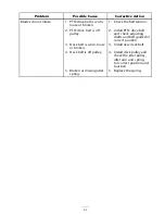
Page 63: ...g 4 Dirt water or stale fuel is in the fuel system 4 Contact an Authorized Service Dealer 1 Engine load is excessive 1 Reduce the ground speed 2 Air cleaner is dirty 2 Clean the air cleaner element 3 Oil level in the crankcase is low 3 Add oil to the crankcase 4 Cooling ns and air passages above the engine are plugged 4 Remove the obstruction from the cooling ns and air passages 5 Vent hole in the...

Page 64: ...mounting bolts are loose 3 Tighten the engine mounting bolts 4 Loose engine pulley idler pulley or blade pulley 4 Tighten the appropriate pulley 5 Engine pulley is damaged 5 Contact an Authorized Service Dealer 6 Blade spindle is bent 6 Contact an Authorized Service Dealer Abnormal vibration 7 Motor mount is loose or worn 7 Contact an Authorized Service Dealer 1 Blade s not sharp 1 Sharpen the bla...

Page 65: ...l PTO drive belt and check adjusting shafts and belt guides for correct position 3 Deck belt is worn loose or broken 3 Install new deck belt 4 Deck belt is off pulley 4 Install deck pulley and check the idler pulley idler arm and spring for correct position and function Blades do not rotate 5 Broken or missing idler spring 5 Replace the spring 65 ...

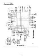
Page 66: ...Schematics Wire Diagram Rev 66 ...

Page 67: ...cheduled for replacement as required maintenance in the written instructions must be warranted for the warranty period of two years If any such part fails during the period of warranty coverage it must be repaired or replaced by The Toro Company Any such part repaired or replaced under the warranty must be warranted for a time not less than the remaining warranty period B Any warranted part that i...

Page 68: ... maintenance service or parts such as lters fuel lubricants tune up parts blade sharpening brake and clutch adjustments Any product or part which has been altered or misused or required replacement or repair due to normal wear accidents or lack of proper maintenance Repairs necessary due to improper fuel contaminants in the fuel system or failure to properly prepare the fuel system prior to any pe...

Reviews: