CAUTION
This machine produces sound levels in
excess of 85 dBA at the operator’s ear and
can cause hearing loss through extended
periods of exposure.
Wear hearing protection when operating this
machine.
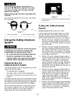
Use protective equipment for your eyes, ears, hands,
feet, and head.
g009027
Figure 11
1.
Wear eye protection.
2.
Wear hearing protection.
Using the Safety-Interlock
System
WARNING
If safety-interlock switches are disconnected
or damaged, the machine could operate
unexpectedly causing personal injury.
•
Do not tamper with the interlock switches.
•
Check the operation of the interlock
switches daily, and replace any damaged
switches before operating the machine.
Understanding the
Safety-Interlock System
The safety-interlock system is designed to prevent the
engine from starting unless:
•
The parking brake is engaged.
•
The blade-control switch (PTO) is disengaged.
•
The motion-control levers are in the N
EUTRAL
-
LOCK
position.
The safety-interlock system also is designed to shut off
the engine when the traction controls are moved from
the locked position with the parking brake engaged or
if you rise from the seat when the PTO is engaged.
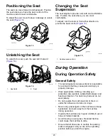
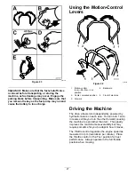
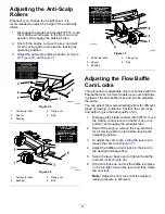
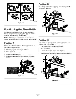
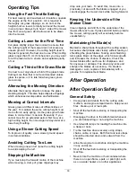
The hour meter has symbols to notify the user when
the interlock component is in the correct position.
When the component is in the correct position, a
triangle lights up in the corresponding square.
g013672
Figure 12
1.
Triangles light up when the interlock components are in the
correct position
Testing the Safety-Interlock
System
Service Interval:
Before each use or daily
Test the safety-interlock system before you use the
machine each time. If the safety system does not
operate as described below, have an Authorized
Service Dealer repair the safety system immediately.
1.
Sitting on the seat, engage the parking brake
and move the blade-control switch (PTO) to the
O
N
position. Try starting the engine; the engine
should not start.
2.
Sitting on the seat, engage the parking brake
and move the blade-control switch (PTO) to the
O
FF
position. Move either motion-control lever
(out of the N
EUTRAL
-
LOCK
position). Try starting
the engine; the engine should not start. Repeat
for the other control lever.
3.
Sitting on the seat, engage the parking brake,
move the blade-control switch (PTO) to the O
FF
position, and move the motion-control levers
to the N
EUTRAL
-
LOCK
position. Now start the
engine. While the engine is running, disengage
the parking brake, engage the blade-control
switch (PTO), and rise slightly from the seat; the
engine should shut off.
4.
Sitting on the seat, engage the parking brake,
move the blade-control switch (PTO) to the O
FF
position, and move the motion-control levers
to the N
EUTRAL
-
LOCK
position. Now start the
engine. While the engine is running, center
either motion control and move (forward or
reverse); the engine should shut off. Repeat for
other motion control.
5.
Sitting on the seat, disengage the parking brake,
move the blade-control switch (PTO) to the O
FF
position, and move the motion-control levers
to the N
EUTRAL
-
LOCK
position. Try starting the
engine; the engine should not start.
22
Summary of Contents for Z Master Professional 5000 Series
Page 13: ...decal136 5508 136 5508 1 Belt routing 13...
Page 78: ...Schematics g021490 Wire Diagram Rev A 78...
Page 79: ...Notes...


