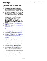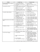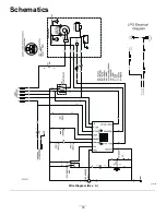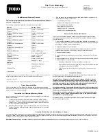
g006530
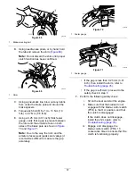
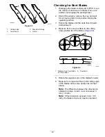
Figure 93
1.
Cutting edge
3.
Wear/slot forming
2.
Curved area
4.
Crack
Checking for Bent Blades
1.
Disengage the blade-control switch (PTO), move
the motion-control levers to the N
EUTRAL
-
LOCK
position, and engage the parking brake.
2.
Shut off the engine, remove the key, and wait
for all moving parts to stop before leaving the
operating position.
3.
Rotate the blades until the ends face forward
and backward.
4.
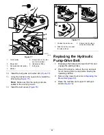
Measure from a level surface to the cutting
edge, position
A
, of the blades (
g000975
Figure 94
1.
Measure here from blade
to hard surface
2.
Position A
5.
Rotate the opposite ends of the blades forward.
6.
Measure from a level surface to the cutting edge
of the blades at the same position as in step
above.
Note:
The difference between the dimensions
obtained in steps
and
must not exceed 3
mm (1/8 inch).
Note:
If this dimension exceeds 3 mm (1/8
inch), the blade is bent and must be replaced.
70
Summary of Contents for Z Master Professional 5000 Series
Page 13: ...decal136 5508 136 5508 1 Belt routing 13...
Page 78: ...Schematics g021490 Wire Diagram Rev A 78...
Page 79: ...Notes...


