Note:
If the blade stays in a horizontal position,
the blade is balanced and can be used.
Note:
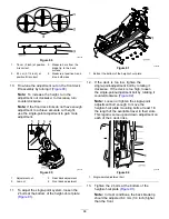
If the blade is not balanced, file some
metal off the end of the sail area only (
).
g000553
Figure 97
1.
Blade
2.
Balancer
3.
Repeat this procedure until the blade is
balanced.
Installing the Blades
1.
Install the blade onto the spindle shaft (
Important:
The curved part of the blade
must be pointing upward toward the inside
of the mower to ensure proper cutting.
2.
Install the spring disk and blade bolt (
).
Note:
The spring-disk cone must be installed
toward the bolt head (
3.
Torque the blade bolt to 115 to 150 N∙m (85 to
110 ft-lb).
g004536
Figure 98
1.
Sail area of the blade
3.
Spring disk
2.
Blade
4.
Blade bolt
Removing the Mower Deck
Lock out the spring-loaded deck arms before servicing
or removing the mower deck.
WARNING
Deck-lift arm assemblies have stored energy.
Removing the deck with out releasing the
stored energy can cause serious injury or
death.
Do not attempt to disassemble the deck from
the front frame without locking out the stored
energy.
1.
Shut off the engine, wait for all of the moving
parts to stop, remove the key, and engage the
parking brake.
2.
Remove the height-adjustment pin and lower
the deck to the ground.
3.
Place the height adjustment pin in the 7.6 cm (3
inch) cutting-height location.
Note:
This locks the deck-lift arms in the lowest
position when the deck is removed and the
stored energy in the deck spring is released.
4.
Remove the belt covers.
5.
Lift up the floor pan and insert a ratchet into the
square hole in the deck idler (
6.
Rotate the deck idler clockwise and remove the
mower belt (
72
Summary of Contents for Z Master Professional 5000 Series
Page 13: ...decal136 5508 136 5508 1 Belt routing 13...
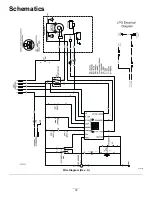
Page 78: ...Schematics g021490 Wire Diagram Rev A 78...
Page 79: ...Notes...


