30
25
30
25
G014921
2
1
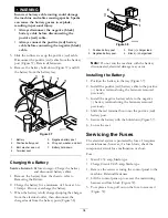
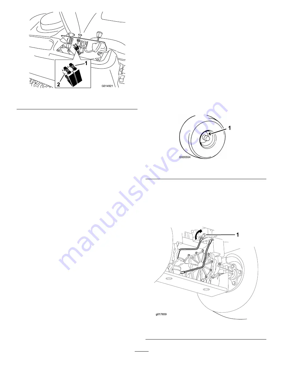
Figure 39
1.
Main-30 amp
2.
Charge circuit-25 amp
4. Return the control panel to its original position. Use
the screws removed previously to secure the panel
to the machine.
Drive System
Maintenance
Checking the Tire Pressure
Service Interval:
Every 25 hours—Check tire pressure.
Maintain the air pressure in the front and rear tires as
specified. Uneven tire pressure can cause uneven cut.
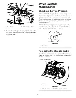
Check the pressure at the valve stem (Figure 40). Check
the tires when they are cold to get the most accurate
pressure reading.
Refer to the maximum pressure suggested by the tire
manufacturer on the sidewall of the caster wheel tires.
Inflate the rear drive wheel tires to 12 psi.
Figure 40
1.
Valve stem
Releasing the Electric Brake
The electric brake can be release by manually rotating the
link arms forward. Once the electric brake is energized
the brake will reset.
To release the brake:
g017659
1
Figure 41
1.
Brake link arm on the electric brake control module
35
Summary of Contents for TimeCutter MX 4260
Page 10: ...119 8874 1 Low speed 2 High speed 10 ...
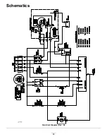
Page 48: ...Schematics g017655 Electrical Diagram Rev A 48 ...
Page 49: ...Notes 49 ...
Page 50: ...Notes 50 ...
Page 51: ...Notes 51 ...

