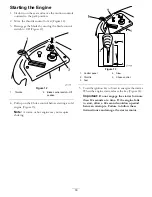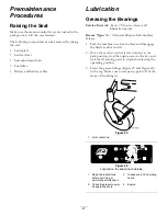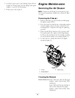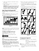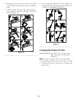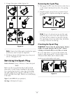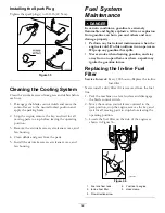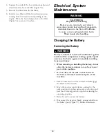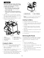
operate as described below, have an Authorized Service
Dealer repair the safety system immediately.
1. While sitting on the seat, with the control levers in
park position, and move the blade control switch to
On. Try starting the engine; the engine should not
crank.
2. While sitting on the seat, move the blade control
switch to Off. Move either motion control lever
to the center, unlocked position. Try starting the
engine; the engine should not crank. Repeat with
the other motion control lever.
3. While sitting on the seat, move the blade control
switch to Off, and lock the motion control levers in
the park position. Start the engine. While the engine
is running, engage the blade control switch, and rise
slightly from the seat; the engine should stop.
4. While sitting on the seat, move the blade control
switch to Off, and lock the motion control levers
in the park position. Start the engine. While the
engine is running, move the motion control levers
to the center, unlocked position, engage the blade
control switch, and rise slightly from the seat; the
engine should stop.
Stopping the Engine
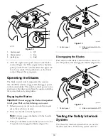
1. Disengage the blades by moving the blade control
switch to Off (Figure 16).
2. Move the throttle lever to between the Fast position
(Figure 13).
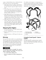
3. Turn the ignition key to Off (Figure 14) and remove
the key.
Driving
Driving the machine benefits from an understanding of
what zero turn radius mower means. The drive wheels
turn independently, powered by hydraulic motors on
each axle; hence one side can turn in reverse while
the other turns forward causing the machine to spin
rather than turn. This vastly improves the machine
maneuverability but may require some adjustment if
the operator is unfamiliar.
WARNING
The machine can spin very rapidly. The operator
may lose control of the machine and cause personal
injury or damage to the machine.
•
Use caution when making turns.
•
Slow the machine down before making sharp
turns.
The throttle control regulates the engine speed as
measured in rpm (revolutions per minute). Placing the
throttle control in the Fast position can be best for
performance. For most applications, operating in the
full throttle position is desirable.
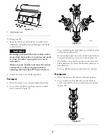
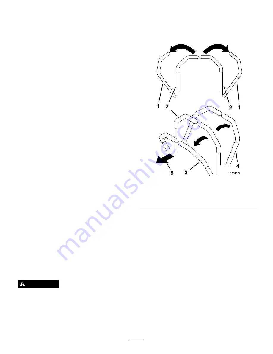
Figure 17
1.
Park (brake) position
4.
Backward
2.
Center unlock position
5.
Front of machine
3.
Forward
Using the Smart Speed
™
Control
System
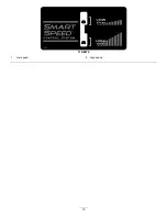
The Smart Speed™ Control System lever, located
below the operating position (Figure 18), gives the
operator a choice to drive the machine at two ground
speed ranges, high and low.
20
Summary of Contents for TimeCutter MX 4260
Page 10: ...119 8874 1 Low speed 2 High speed 10 ...
Page 48: ...Schematics g017655 Electrical Diagram Rev A 48 ...
Page 49: ...Notes 49 ...
Page 50: ...Notes 50 ...
Page 51: ...Notes 51 ...

