


Adjusting the Cutting Unit
Auto-Limited Lift
Note:
You enable the cutting-unit Auto Limited Lift
feature in the settings menu of the InfoCenter.
•
Manual limited lift uses the 3 lift-control switches,
and is always available regardless of auto-limited
lift setting in the InfoCenter.
•
When cutting-unit Auto Limited Lift is enabled,
driving the machine in reverse causes the cutting
units to automatically raise to the limited-lift
position.
•
The cutting units return to the floating position
when driving the machine forward.
To raise the cutting units to the limited-lift position,
momentarily pull the lift-control switches.
Note:
The cutting-unit drives disengage immediately,
and the cutting units raise to approximately 150 mm
(6 inches) above ground level.
Auto-limited lift operates with the cutting units lowered
and rotating.
Cutting Unit Drive
The cutting unit drive engages only when you sit in
the operator’s seat; refer to
Presence Seat Switch (page 20)
.
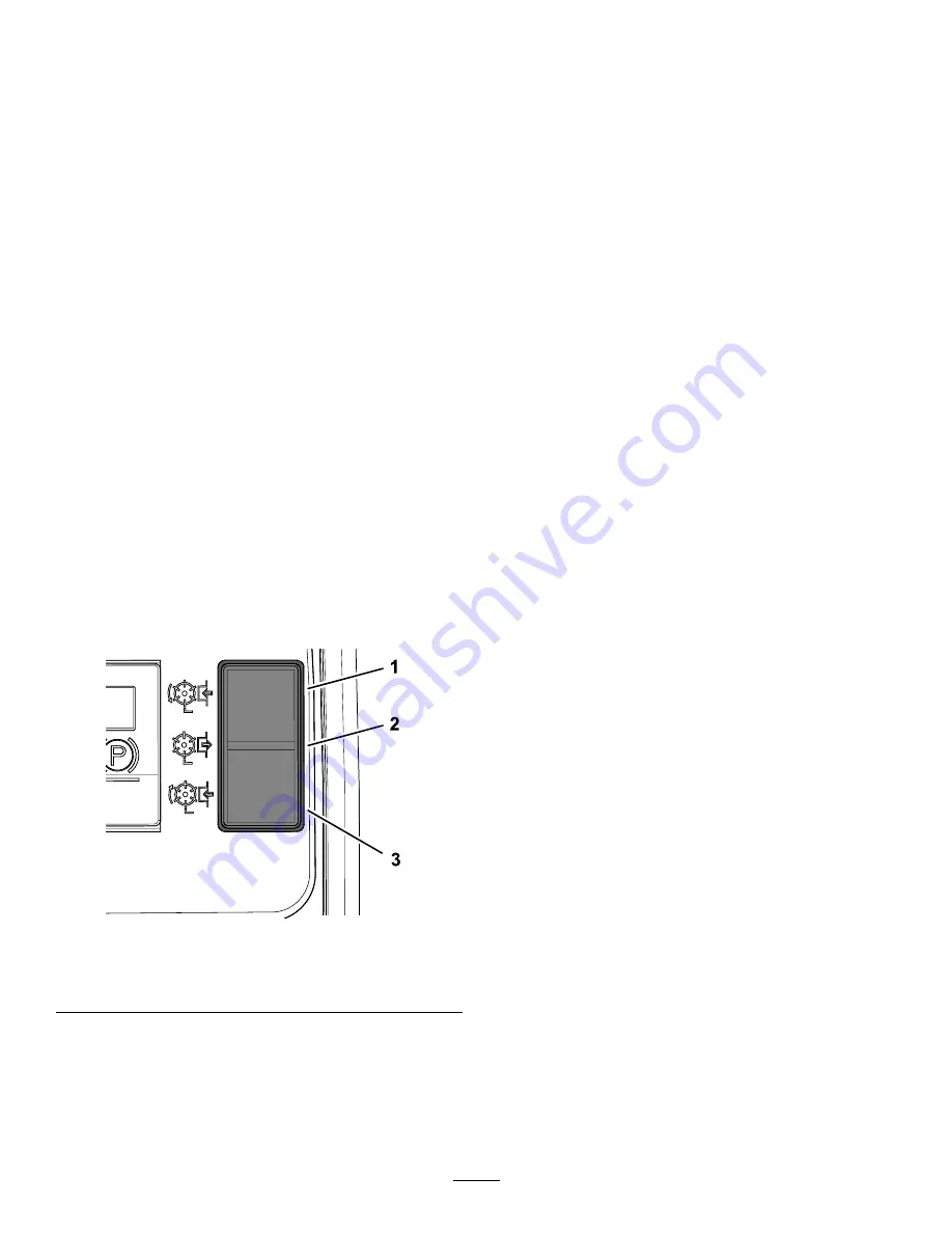
g292363
Figure 28
1.
Forward
3.
Reverse
2.
Off
Engaging the Cutting Unit Drive
for Forward Rotation
Press the top of the cutting unit drive switch to the
forward rotation position (
Engaging the Cutting Unit Drive
for Reverse Rotation
Press the bottom of the cutting unit drive switch to the
reverse rotation position (
Disengaging All Cutting Unit
Drives
Press the cutting unit drive switch to the middle
position (
Lowering the Cutting Units
Press the cutting unit drive switch to the forward
rotation position. Press the lift-control switch(s) to the
L
OWER
position. The cutting units run when the they
are approximately 150 mm (6 inches) above ground
level.
Adjusting the Weight
Transfer/Traction
Assistance
A variable hydraulic weight transfer system provides
improved tire grip with the grass surface—traction
assistance.
Hydraulic pressure from the cutting-unit lift system
provides a lifting force that reduces the weight of the
cutting units on the ground and transfers the weight
downward to the tires. This action is known as weight
transfer.
Note:
Adjust the amount of weight transfer to suit
operating conditions.
1.
Open the hood.
27


