background image

Operation

14

Adjusting Dial-A-Height

The Dial-A-Height control (Fig. 19) is used to limit
the downward travel of the attachment. The
Dial-A-Height knob is rotated to change the location
of this stop, up or down.

1.

Raise the attachment lift lever: Refer to Raising
Attachments. In the raised, position the
Dial-A-Height knob (Fig. 19) can be rotated to
change the stop location. Turn clockwise to raise
and counterclockwise to lower the height of the
attachment.

2.

The Dial-A-Height indicator (Fig. 19) will show
the change, high to low, in attachment lift height
as adjustment is made.

Adjusting Anti-Scalp Wheels

The anti-scalp wheels must be adjusted in the proper
hole location for each height-of-cut position.

1.

After adjusting height-of-cut. raise the
attachment lift lever: Refer to Raising
Attachments.

2.

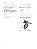
Remove hairpin cotter and pin to change hole
location (Fig. 21).

3.

Select a hole position so the anti-scalp wheel is
3/8” (9.5 mm) off the ground for the
height-of-cut to be used (Fig. 21).

4.

Insert pin and secure with hairpin cotter.

5.

Repeat adjustment on other anti-scalp wheels.

1233

1

2

3

Figure 21

1.

Wheel

2.

Pin

3.

Hair pin Cotter

Summary of Contents for 78253

Page 1: ...Operator s Manual English GB Form No 3326 461 Wheel Horse 52 Mower for Lawn and Garden Tractors Model No 78253 200000001 Up ...

Page 2: ...No Serial No The warning system in this manual identifies potential hazards and has special safety messages that help you and others avoid personal injury even death DANGER WARNING and CAUTION are signal words used to identify the level of hazard However regardless of the hazard be extremely careful DANGER signals an extreme hazard that will cause serious injury or death if the recommended precaut...

Page 3: ...ope 10 Removing the Mower 11 Operation 12 Side Discharge 12 Operating the Power Take Off PTO 12 Attachment Lift Lever 13 Page Attachment Power Lift 13 Adjusting Dial A Height 14 Adjusting Anti Scalp Wheels 14 Tips for Mowing Grass 15 Maintenance 16 Service Interval Chart 16 Cutting Blade 17 Greasing and Lubrication 19 Blade Drive Belt 19 Power Take Off PTO Belt 20 Washing Underside of Mower 20 Sto...

Page 4: ...located near any area of potential danger Replace any decal that is damaged or lost ON GRASS DEFLECTOR Part No 93 7317 ON MOWER REAR CENTER Part No 94 4937 ON MOWER LEFT AND DISCHARGE CHUTE Part No 93 7316 NEXT TO GAGE WHEELS Part No 93 7282 ON MOWER LEFT SIDE Part No 94 2543 UNDER GRASS DEFLECTOR Part No 93 7009 ...

Page 5: ...2 2 2 Install front mount to mower Grass deflector Spring Bolt 3 8 24 x 3 1 2 89 mm Locknut 3 8 24 1 2 2 2 Install grass deflector Up stop 1 Install mower up stop Hairpin cotter 3 3 8 85 mm Washer 3 4 19 mm Link pin Hairpin cotter2 9 16 65 mm Washer 2 2 1 3 3 Install mower to tractor Operator s Manual Warranty card 1 1 Read before operating IMPORTANT If you have a 1999 or earlier tractor and are i...

Page 6: ...houlder bolt 5 Lock nut 3 8 with patch 3 Install link bracket between mower bracket and carrier lift arm Fig 2 4 Secure with 1 2 washers and 1 26 mm cotter pins Fig 2 2 1 3 4 m 4617 Figure 2 1 Link Bracket 2 Carrier lift arm 3 Washer 1 2 4 Cotter pin 1 26 mm 5 Rotate adjustable links so bolt heads are up and place between brackets as shown on front of the mower Fig 3 6 Secure to brackets with 1 2 ...

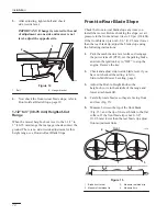
Page 7: ...4 1 Bracket 2 Spring hook end 3 space for spring 4 Grass deflector 5 Bolt 3 8 3 1 2 89 mm 6 Lock nut 3 8 POTENTIAL HAZARD Without the grass deflector discharge cover or complete grass catcher assembly mounted in place you and others are exposed to blade contact and thrown debris WHAT CAN HAPPEN Contact with rotating mower blade s and thrown debris will cause injury or death HOW TO AVOID THE HAZARD...

Page 8: ... attachment lift to the full UP position Refer to Operation Attachment Lift page 13 5 Remove E ring washer and lift link from front lift arm Fig 6 6 Hold front lift arm up until stop contacts frame Fig 6 7 Push back hard on lift rod to raise linkage and check location of lift rod compared to mounting hole location 8 Adjust length of lift rod by turning in out of trunnion so end just slides into mo...

Page 9: ...usly removed hardware 13 Torque bolt to 55 ft lbs 75 N m 1 2 4 3 5 6 m 4828 Figure 7 1 Single Pulley Clutch Included with deck 2 Engine 3 Bolt 4 Washer 5 Clutch Plug in 6 Upstop 14 Install retainer clip and clutch plug in to right side of frame as shown in figure 8 Make sure there is no slack in plug in wire between clutch and retainer clip 1 2 3 m 4633 4 Figure 8 1 Clutch Plug in 2 Right side of ...

Page 10: ...hairpin cotter Fig 10 1 7 2 3 4 5 6 6 5 8 M 3644 Figure 10 1 Lift arm 2 Washer 3 4 3 Hair pin cotter large 4 Attachment lift 5 Washer 1 2 6 Hair pin cotter small 7 Link pin 8 Carrier Lift Arm POTENTIAL HAZARD Movement of powerlift can injure a person when aligning deck with lift arms WHAT CAN HAPPEN Contact between carrier lift arm and attachment lift can cause serious injury HOW TO AVOID THE HAZA...

Page 11: ... be level from side to side Check the side to side level any time you install the mower or when you see an uneven cut on your lawn Before you level the mower set the air pressure in the front and rear tires to 20 psi 138 kPa 3 to 4 76 102 mm Height of Cut Range When the mower height of cut is set to the 3 to 4 76 102 mm range the mower is suspended from the tractor 1 Park the machine on a level su...

Page 12: ...psi 138 kPa If the front blade tip is not 0 3 8 0 9 5 mm lower than the rear blade tip adjust the blade slope using the following instructions 1 Park the machine on a level surface disengage the power take off PTO set the parking brake and turn the ignition key to OFF to stop the engine Remove the key 2 Check and adjust side to side blade level if you have not checked the setting refer to Side to ...

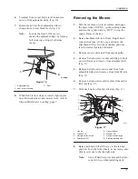
Page 13: ...n Dial a Height knob counterclockwise all the way and lower the attachment lift lever to the mounting position refer to tractor Operator s Manual 3 Remove mower drive belt from engine pulley 4 Remove hairpin cotter washer and link pin from carrier lift arm and remove from attachment lift Fig 17 5 Remove hairpin cotter and washer from front adjustable link s and remove from front lift arm Fig 17 6 ...

Page 14: ... key to OFF Also remove the key and pull the wire off the spark plug s 1 The mower has a hinged grass deflector that disperses clippings to the side and down toward the turf Operating the Power Take Off PTO The power take off PTO engages and disengages power to the electric clutch While the ignition key is in the RUN or LIGHTS positions and the power take off PTO is engaged ON the PTO light in the...

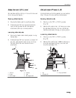
Page 15: ... lift lever forward to lower attachment 1205 3 2 4 5 6 1 Figure 19 1 Lift lever 2 Button 3 Dial A Height 4 Indicator 5 High 6 Mounting position Attachment Power Lift The attachment power lift optional on some models Fig 20 is used to raise and lower attachments Raising Attachments 1 Turn key to the ON or RUN position Fig 20 2 Push the lift switch in the UP direction to raise the attachment lift Fi...

Page 16: ...Dial A Height indicator Fig 19 will show the change high to low in attachment lift height as adjustment is made Adjusting Anti Scalp Wheels The anti scalp wheels must be adjusted in the proper hole location for each height of cut position 1 After adjusting height of cut raise the attachment lift lever Refer to Raising Attachments 2 Remove hairpin cotter and pin to change hole location Fig 21 3 Sel...

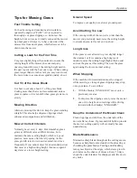
Page 17: ...id summer mow less frequently If you cannot mow for an extended period first mow at a high cutting height then mow again 2 days later at a lower height setting Ground Speed To improve cut quality use slower ground speed Avoid Cutting Too Low If the cutting width of the mower is wider than the mower you previously used raise the cutting height to ensure uneven turf is not cut too short Long Grass I...

Page 18: ...X X Chipped Surfaces paint X POTENTIAL HAZARD If you leave the key in the ignition switch someone could start the engine WHAT CAN HAPPEN Accidental starting of the engine could seriously injure you or other bystanders HOW TO AVOID THE HAZARD Remove the key from the ignition switch and pull the wire off the spark plug before you do any maintenance Also push the wire aside so it does not accidentall...

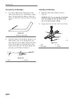
Page 19: ...the Mower page 11 2 Inspect the cutting edges Fig 22 If the edges are not sharp or have nicks remove the blade s and sharpen them refer to Sharpening the Blade s page 18 3 Inspect the blade s especially the curved area Fig 22 If you notice any damage wear or a slot forming in this area Fig 22 immediately install a new blade 151 1 2 3 Figure 22 1 Cutting edge 2 Curved area 3 Wear slot forming Remov...

Page 20: ...g 25 If the blade stays in a horizontal position the blade is balanced and can be used If the blade is not balanced file some metal off the back side of the blade Repeat this procedure until the blade is balanced 1 2 Figure 25 1 Blade 2 Balancer Installing the Blade s 1 Install the blade blade stiffener and bolt Fig 26 IMPORTANT The curved part of the blade must be pointing toward the inside of th...

Page 21: ... a rag Make sure to scrape any paint off the end of the fitting s 3 Connect a grease gun to the fitting Pump grease into the fittings 4 Wipe up any excess grease Where to Add Grease 1 Lubricate the blade spindles idler pulley arm and gage wheels Fig 27 M 2429 Figure 27 Blade Drive Belt Removing the Blade Drive Belt 1 Remove the mower refer to Removing the Mower page 11 2 Remove pulley cover mounti...

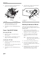
Page 22: ...4 Adjust belt guide so distance between belt and guide is 1 8 4 mm Fig 30 m 2418 3 2 1 Figure 30 1 Left pully cover 2 PTO belt 3 1 8 4 mm Washing Underside of Mower After each use wash the underside of the mower to prevent grass build up for improved mulch action and clipping dispersal 1 Park the machine on a hard level surface disengage the power take off PTO and turn the ignition key to OFF to s...

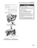
Page 23: ... 2 3 4 Figure 31 1 Washout fitting left 2 Coupling not supplied 3 Hose 4 Washout fitting right POTENTIAL HAZARD A broken or missing washout fitting could expose you and others to thrown objects or blade contact WHAT CAN HAPPEN Contact with thrown debris or blade contact will cause injury or death HOW TO AVOID THE HAZARD Replace broken or missing washout fitting immediately before using mower again...

Page 24: ...battery 2 Wash the underside of the mower refer to Washing Underside of Mower page 20 3 Check the condition of the blade s refer to Cutting Blade page 17 4 Check the condition of the blade drive belt 5 Grease the mower deck refer to Greasing and Lubrication page 19 6 Check and tighten all bolts nuts and screws Repair or replace any part that is damaged or defective 7 Paint all scratched or bare me...

Page 25: ...pulley 5 Engine pulley is damaged 5 Contact Authorized Service Dealer Blade s does not rotate 1 Blade drive belt is worn loose or broken 1 Install new blade drive belt 2 Blade drive belt is off pulley 2 Install blade drive belt and check idler pulley and belt guides for correct position 3 PTO belt is worn loose or broken 3 Install new PTO belt Uneven cutting height 1 Tire pressure is incorrect 1 S...

Page 26: ...Troubleshooting 24 ...

Page 27: ...Troubleshooting 25 ...

Page 28: ...Troubleshooting 26 ...

Reviews: