Toro 31598N Operator'S Manual Download Page 18

Figure 8

1.

Eccentric notch

Tighten the bolt and nut for this eccentric to 149 N-m
(110 ft-lb).

Adjust the forward eccentric until it just makes contact
with the inner slot surface of the winglet pivot brackets.

Tighten the bolt and nut for this eccentric to 149 N-m
(110 ft-lb).

Repeat the procedure on the opposite winglet. Refer to
Adjusting the Cutting Unit Pitch procedure in Mower
Maintenance.

5

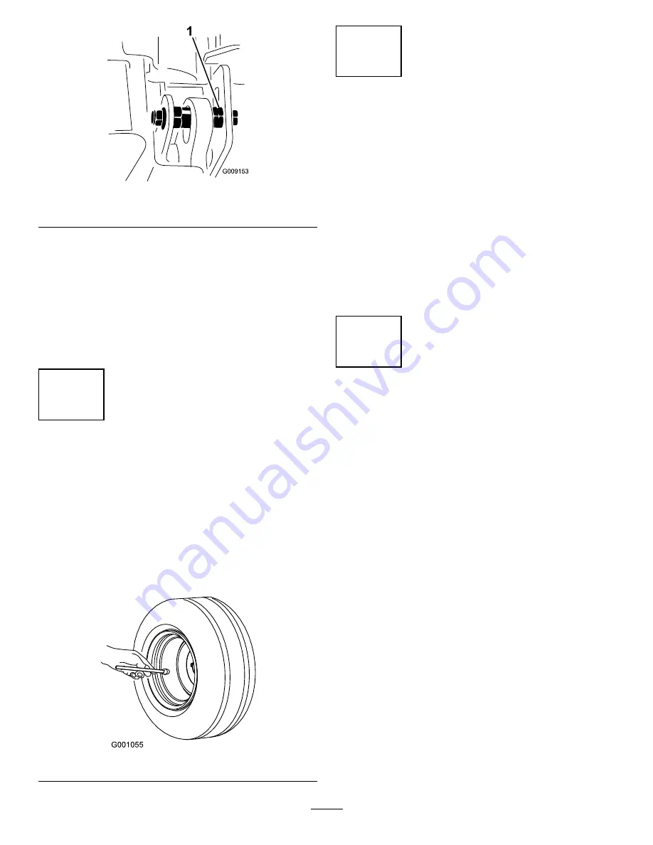
Checking the Tire Pressure

No Parts Required

Procedure

Check the air pressure in all the tires before operating the
machine. The correct air pressure in the front tires is 345 kPa
(50 psi) and the rear tires is 207 kPa (30 psi) (

Figure 9

).

Important:

Maintain pressure in all tires to ensure a

good quality-of-cut and proper machine performance.
Do not under-inflate.

Figure 9

6

Checking the Fluid Levels

No Parts Required

Procedure

1.

Check the engine oil level before starting the engine,
refer to Checking the Engine Oil Level in Engine
Maintenance.

2.

Check the hydraulic fluid level before starting the
engine, refer to Checking the Hydraulic Fluid Level in
Hydraulic System Maintenance.

3.

Check the cooling system before starting the engine;
refer to Checking the Cooling System in Cooling
System Maintenance.

7

Greasing the Machine

No Parts Required

Procedure

Before the machine is operated, it must be greased to
ensure proper lubricating characteristics; refer to Greasing
the Bearings and Bushings procedure in Lubrication in the
Maintenance Section. Failure to properly grease the machine
will result in premature failure of critical parts.

18


Summary of Contents for 31598N

Page 1: ...No 3391 812 Rev A Groundsmaster 5900 and 5910 Rotary Mower Model No 31598N Serial No 315000001 and Up Model No 31599N Serial No 315000001 and Up Register at www Toro com Original Instructions EN 3391...

Page 2: ...ass and other growth alongside highways or for agricultural uses Read this information carefully to learn how to operate and maintain your product properly and to avoid injury and product damage You a...

Page 3: ...5 Fuel System Maintenance 45 Servicing the Fuel System 45 Servicing the Water Separator 45 Replacing the Fuel Filter 46 Electrical System Maintenance 47 Fuses 47 Battery Care 48 Jump Starting Battery...

Page 4: ...be used and remove all objects which may be thrown by the machine Replace faulty silencers mufflers Before using always visually inspect to see that the blades blade bolts and cutting assembly are no...

Page 5: ...chment before refuelling before making height adjustment unless adjustment can be made from the operators position Reduce the throttle setting before stopping engine and if the engine is provided with...

Page 6: ...long pants is advisable and required by some local ordinances and insurance regulations Keep hands feet and clothing away from moving parts and the mower discharge area and underside of the mower whil...

Page 7: ...ke sure of optimum performance and continued safety certification of the machine use only genuine Toro replacement parts and accessories Replacement parts and accessories made by other manufacturers c...

Page 8: ...ess the brake 3 Read the Operators Manual 6 Parking brake 115 5459 1 Electric shock hazard do not remove cover keep cover in place 106 6754 1 Warning do not touch the hot surface 2 Cutting dismemberme...

Page 9: ...perator s Manual 5 Mid idle 10 Decrease engine speed 93 6674 1 Crushing hazard hand read the instructions before servicing or performing maintenance 93 6687 1 Do not step here 120 6604 1 Thrown object...

Page 10: ...er cutting units left 4 Headlight switch location 10 Lower cutting units center 5 Cruise control engage 11 Lower cutting units right 6 Cruise control disengage 114 0922 114 0922 1 Belt routing 114 097...

Page 11: ...from moving parts keep all guards in place 7 Tipping hazard lower the cutting unit when driving down slopes slow machine before turning do not turn at high speeds 8 Warning lock the parking brake sto...

Page 12: ...azard 6 Keep bystanders a safe distance from the battery 2 No fire open flame or smoking 7 Wear eye protection explosive gases can cause blindness and other injuries 3 Caustic liquid chemical burn haz...

Page 13: ...Start Advisory clears on the Info Center then turn the ignition key to Start 2 Read the Operators Manual to stop the engine move the throttle lever to slow disengage the PTO set the parking brake wait...

Page 14: ...the Operator s Manual for more information on fuses 5 Head lights 25A 2 Electrical power accessory 15A 6 Condenser fan and A C clutch 30A 3 Dome light 15A 7 Fan 15A 4 Windshield wiper fluid 15A 8 Wor...

Page 15: ...Operator Training Material 1 Provide the operator with information on the use and maintenance of the machine Parts Catalog 1 Ordering parts Declaration of Conformity 1 Note Determine the left and righ...

Page 16: ...procedure on left winglet Figure 4 1 Winglet 4 Eccentric 2 Hinge pin 5 Lower hole 3 Bolt 7 Install the winglet belts as follows Start the belt around the winglet spindle pulley and the front deck spin...

Page 17: ...U bolt 5 Adjust the nuts to raise or lower the rear of the cutting unit so that the front and rear blade tips have the same measurement Tighten the jam nuts 6 Proceed to procedure 4 and level the wing...

Page 18: ...es to ensure a good quality of cut and proper machine performance Do not under inflate Figure 9 6 Checking the Fluid Levels No Parts Required Procedure 1 Check the engine oil level before starting the...

Page 19: ...switch to activate the right turn signal The center position is off Hi Lo Range Speed Switch Press the front of the switch Figure 10 to select high speed range Press the rear of the switch to select l...

Page 20: ...iddle position of the switch enables the cruise control function and the front of the switch sets the desired ground speed Note Pressing either brake pedal or moving the traction pedal into the revers...

Page 21: ...re in the cab Figure 13 Figure 13 1 Wind shield wiper switch 3 Fan control 2 Air conditioning switch 4 Temperature control Wind Shield Latch Lift up on latches to open the wind shield Figure 14 Press...

Page 22: ...splay indicates that the parking brake is actuated Figure 16 PTO Indicator This display indicates Figure 16 when the PTO in engaged Fan Reverse Indicator This display indicates Figure 16 when the fan...

Page 23: ...e Service Interval Indicator 1 Press and hold the far right button on the Info Center 2 The Main Menu screen will come up Select SERVICE using the 2 buttons on the left press the button below the righ...

Page 24: ...ated 2 Select low range 3 Set parking brake Electronics Issues 1 Fix High Low range switch 2 Controller firmware incompatible 3 Blown fuse 4 HHDT ready Engine 1 Lower engine speed 2 Wait to shutoff en...

Page 25: ...critical sensor error 2 Fix critical voltage error 3 Move forward 4 Move traction pedal to neutral 5 Release parking brake 6 Operator must be seated For Traction Assist 1 Must be in low range 2 Opera...

Page 26: ...length 445 cm 175 inches Minimum ground clearance at machine centerline 24 cm 9 5 inches Wheel tread to center of tire front 160 cm 63 inches rear 142 cm 56 inches Wheel tread to outside of tire front...

Page 27: ...ge the engine WARNING Fuel is harmful or fatal if swallowed Long term exposure to vapors can cause serious injury and illness Avoid prolonged breathing of vapors Keep face away from nozzle and fuel ta...

Page 28: ...tires are 207 kPa 30 psi Figure 22 Important Maintain pressure in all tires to ensure a good quality of cut and proper machine performance Do not under inflate Check the air pressure in all the tires...

Page 29: ...2 inch spacers onto the shaft to get the desired height of cut Note The shim washers may be used in any combination above or below the castor arm hub as required to achieve the desired height of cut...

Page 30: ...ut or higher the axle bolt should be installed in the bottom castor fork hole to prevent grass buildup between the wheel and the fork When operating at heights of cut lower than 64 mm 2 1 2 inch and g...

Page 31: ...holes on the other side of the mower 4 Torque the screw at the front of each skid to 9 to 11 N m 80 to 100 in lb Adjusting the Cutting Unit Anti Scalp Rollers The cutting unit gage wheels and roller...

Page 32: ...its and compare These numbers should be within 3 mm 1 8 inch of each other Make no adjustment at this time 2 Position blade side to side on inside spindle of side cutting unit and corresponding outsid...

Page 33: ...brake is set Remove your foot from the traction pedal and ensure that it is in neutral 2 Set the throttle switch to the low idle position 3 Turn the ignition key to the Run position The air intake hea...

Page 34: ...dal out of the neutral position The traction drive should not function If the traction drive still functions there is a malfunction in the interlock system that should be corrected before beginning op...

Page 35: ...8 Figure 38 1 Front jacking point 2 On the rear of the machine at the center of the axle Figure 39 Figure 39 1 Rear jacking point Tie Downs Under the front of the operator s platform 2 places Figure 4...

Page 36: ...the machine However use them carefully especially on soft or wet grass because the turf may be torn accidentally Another benefit of the brakes is to maintain traction For example in some slope conditi...

Page 37: ...hes when transporting over long distances rough terrain or when trailering Figure 45 1 Transport latch After Operating To ensure optimum performance clean the underside of the mower housing after each...

Page 38: ...om the engine compartment radiator and oil cooler Every 100 hours Inspect the cooling system hoses Every 250 hours Torque the wheel lug nuts Change the engine oil and filter Service the spark arrestor...

Page 39: ...e 46 Premaintenance Procedures Inner Wing Deck Covers Removal 1 Lower the wing deck onto a level surface 2 Disengage the cover latch 3 Remove the bolt securing the belt cover if so equipped 4 Lift the...

Page 40: ...latch Lubrication Greasing the Bearings and Bushings Service Interval Before each use or daily Lubricate castor arm bushings Every 50 hours Lubricate all grease fittings The machine has grease fitting...

Page 41: ...51 Figure 52 Figure 53 Front Cutting Unit Castor fork shaft bushings 2 Figure 54 Spindle shaft bearings 5 located on spindle housing Figure 54 Idler arm pivot bushings 3 located on the idler pivot sh...

Page 42: ...5 Figure 55 Side Cutting Units per side Castor fork shaft bushing 4 Figure 56 Spindle shaft bearings 3 each located on spindle housing Figure 56 Idler arm pivot bushings 2 located on the idler pivot s...

Page 43: ...r and reinstall cover Do not remove air filters Servicing the Air Cleaner Filter 1 Before removing the filter use low pressure air 40 psi clean and dry to help remove large accumulations of debris pac...

Page 44: ...ne for further recommendations Note The best time to check the engine oil is when the engine is cool before it has been started for the day If it has already been run allow the oil to drain back down...

Page 45: ...level is 6 to 13 mm 1 4 to 1 2 inch below the bottom of the filler neck This empty space in the tank allows the fuel to expand Never smoke when handling fuel and stay away from an open flame or where...

Page 46: ...er head by hand only Do not use tools 9 Close the drain plug 10 Connect the water sensor electrical connector from the bottom of the water separator 11 With the vent plug still loosened operate the pr...

Page 47: ...RNING If installing an auxiliary accessory to the machine the only approved locations to source power are the traction unit fuse block Figure 69 or the cab fuse block Figure 71 A maximum of 10 amps is...

Page 48: ...connected before welding on the machine Note Check the battery condition weekly or after every 50 hours of operation Keep the terminals and the entire battery case clean because a dirty battery will d...

Page 49: ...n plug 3 o clock position 2 Remove the plug at the 3 o clock position Figure 73 Oil level should be within 6 mm 1 4 inch of the check plug hole 3 If the oil level is low remove the plug at the 12 o cl...

Page 50: ...ure on the opposite planetary brake assembly Checking the Rear Wheel Toe In Service Interval Every 1 000 hours Check the rear wheel toe in After every 1000 operating hours or annually check the rear w...

Page 51: ...ixed with distilled water 50 50 blend or Glycol based coolant mixed with good quality water 50 50 blend as listed in the Cummins Manual CaCO3 MgCO3 170 ppm Chloride 40 ppm CI Sulfer 100 ppm SO4 DANGER...

Page 52: ...ts 4 Pivot the oil cooler back into position Secure it to the frame with the latches and close the hood Brake Maintenance Adjusting the Service Brakes Adjust the service brakes when there is more than...

Page 53: ...Every 1 000 hours Replace the drive blade belts The blade drive belt tensioned by the spring loaded idler pulley is very durable However after many hours of use the belt will show signs of wear Signs...

Page 54: ...rom the top of the cutting unit and set the covers aside 2 Remove the bolts securing the hydraulic motor to the cutting unit Figure 83 Lift the motor off of the cutting unit and lay it on top of the c...

Page 55: ...imal performance in a wide range of temperature conditions For operation in consistently high ambient temperatures 65 F 18 C to 120 F 49 C ISO VG 68 hydraulic fluid may offer improved performance Prem...

Page 56: ...uid flow into the pan Install the drain plug when the hydraulic fluid stops draining Figure 90 1 Hydraulic filter 3 Hydraulic tank drain plug 2 Hydraulic filter 4 Clean the area around the filter moun...

Page 57: ...The test ports are used to test the pressure in the hydraulic circuits Contact your local Toro distributor or refer to the Toro Service Manual for assistance Mower Maintenance Pivoting Tilting the Fr...

Page 58: ...r than the front 1 Position the machine on a level surface on the shop floor 2 Set the cutting unit to the desired height of cut 3 Make sure the winglets are level to the front deck and the front deck...

Page 59: ...he top of the castor spindle Note Record the position of the washers and spacers before removal so the deck pitch does not have to be readjusted 3 Pull the castor spindle out of the mounting tube Allo...

Page 60: ...to prevent it from accidentally falling 2 Rotate the blade until the ends face forward and backward Figure 99 Measure from the inside of the cutting unit to the cutting edge at the front of the blade...

Page 61: ...hredded Sharpen the cutting edges to correct this condition 1 Position the machine on a level surface Raise the cutting unit engage the parking brake put the traction pedal in neutral make sure the PT...

Page 62: ...sure to measure all of the blades 5 Check that deck is level side to side and adjust as required 6 Install the belt covers Miscellaneous Maintenance Servicing the Spark Arrestor Muffler Service Inter...

Page 63: ...Every 250 hours Clean more frequently in extremely dusty or dirty conditions 1 Stop the engine and remove the key 2 Remove the 6 nuts and washers from the bottom of the rear of the cab Figure 105 1 1...

Page 64: ...terminals and battery posts with Grafo 112X skin over grease Toro Part No 505 47 or petroleum jelly to prevent corrosion D Slowly recharge the battery every 60 days for 24 hours to prevent lead sulfat...

Page 65: ...Notes 65...

Page 66: ...Notes 66...

Page 67: ...Notes 67...

Page 68: ...ot limited to damage to seats due to wear or abrasion worn painted surfaces scratched decals or windows etc Parts Parts scheduled for replacement as required maintenance are warranted for the period o...

Reviews: