Toro 315000001 Operator'S Manual Download Page 1

Form No. 3393-275 Rev A
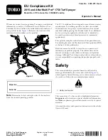
EU Compliance Kit

2015 and After Multi Pro

®

1750 Turf Sprayer

Model No. 41155—Serial No. 315000001 and Up

Operator's Manual

Whenever you need service, genuine Toro parts, or additional
information, contact an Authorized Service Dealer or Toro
Customer Service and have the model and serial numbers of
your product ready.

Figure 1

illustrates the location of the

model and serial numbers on the product.

Figure 1

Model No.

Serial No.

Note:

Determine the left and right sides of the machine

from the normal operating position.

The EU Compliance Kit is designed to meet German safety
requirements by enabling operators to clean out residual
chemicals from the sprayer system and clean the external
machine while bypassing the chemical tank. It is a dedicated
kit for a turf spray application vehicle and is intended to
be used by professional, hired operators in commercial
applications.

This product complies with all relevant European directives.
For details, please see the Declaration of Incorporation (DOI)
at the back of this publication.

Read this manual carefully to learn how to operate and
maintain your product properly. The information in this
manual can help you and others avoid injury and product
damage. Although Toro designs and produces safe products,
you are responsible for operating the product properly and
safely.

Safety

This manual identifies potential hazards and has safety
messages identified by the safety alert symbol (

Figure 2

),

which signals a hazard that may cause serious injury or death
if you do not follow the recommended precautions.

Figure 2

1.

Safety alert symbol

This manual uses 2 other words to highlight information.

Important

calls attention to special mechanical information

and

Note

emphasizes general information worthy of special

attention.

Also read the safety and operation instructions in the vehicle

Operator’s Manual

.

© 2014—The Toro® Company
8111 Lyndale Avenue South
Bloomington, MN 55420

Register at www.Toro.com.

Original Instructions (EN)

Printed in the USA

All Rights Reserved

*3393-275* A


Summary of Contents for 315000001

Page 1: ...with all relevant European directives For details please see the Declaration of Incorporation DOI at the back of this publication Read this manual carefully to learn how to operate and maintain your...

Page 2: ...he spray tank Do not eat drink or smoke while working with chemicals Always wash your hands and other exposed areas as soon as possible after finishing the work Properly dispose of unused chemicals an...

Page 3: ...below to verify that all parts have been shipped Procedure Description Qty Use 1 No parts required Prepare the machine Carriage bolt 5 16 x 1 inch 2 Spray gun bracket 1 Clamp 2 Flanged locknut 5 16 i...

Page 4: ...Install the rinse pump 4 way valve 1 Straight barbed fitting 1 inch NPT x 3 4 inch 1 90 degree barbed fitting 1 inch NPT x 3 4 inch 2 Straight barbed fitting 3 4 inch NPT x 1 2 inch 1 Reducer fitting...

Page 5: ...nch 1 10 Hose clamp 2 Install the hose between the ball valve and the 4 way valve Hose 1 9 x 61 cm 3 4 x 24 inch 1 11 Hose clamp 2 Install the hose between the pressure filter assembly and the 4 way v...

Page 6: ...ns and precautions Keep chemicals away from your skin Should contact occur wash the affected area thoroughly with soap and clean water Wear goggles and any other protective equipment recommended by th...

Page 7: ...langed locknut 5 16 inch 2 Remove and retain the bolt 3 8 x 5 inch washers and flanged locknut that secure the front tank straps at the top of the tank Figure 5 Note Retain the bolt 3 8 x 5 inch washe...

Page 8: ...age bolt at the right front tank strap assemble the spray gun bracket to the carriage bolt and secure the bracket with the flanged locknut Figure 7 Figure 7 1 Carriage bolts 3 8 x 1 1 4 inch 3 Spray g...

Page 9: ...ut 2 Bulkhead fitting positioned G Install a 90 barbed fitting onto the bulkhead fitting and secure the barbed fitting with a retainer Figure 12 Note Rotate the 90 barbed fitting so that it faces rear...

Page 10: ...ocket molded into the top rear part of the rinse tank Figure 15 1 Flanged locknut 3 8 inch 4 Right tank bracket slotted flange angled down from left to right 2 Hose mount 5 Carriage bolt 3 8 x 1 1 4 i...

Page 11: ...the spray system during operation Note Drilling counter clockwise will make drilling easier Installing the Nozzles Note Apply PTFE tape to the threads of the taper threaded fittings used in the spraye...

Page 12: ...pper inboard holes of the right rear tank strap Figure 20 Note Loosely thread a flanged locknuts 3 8 inch onto the carriage bolt 1 2 3 1 g024697 4 Figure 20 1 Nut 3 Valve mount 2 Carriage bolt 4 Hairp...

Page 13: ...e pump and rinse pump mounting bracket to the valve mount Figure 23 with the 4 bolts 1 4 x 1 3 4 inch 4 washers 1 4 inch and 4 serrated flange nuts 1 4 inch 1 2 3 4 5 7 6 g025042 8 Figure 23 1 Serrate...

Page 14: ...straight barbed fitting 3 4 inch NPT x 1 2 inch into the 4 way valve as shown in Figure 24 Important Align the 90 barbed fittings as shown in Figure 24 1 2 4 3 5 g024698 Figure 24 1 90 barbed fitting...

Page 15: ...age bolt 2 Flanged locknut 5 Positive battery cable 3 Positive battery terminal 2 Remove the flanged locknut carriage bolt and positive battery cable from the battery Figure 28 3 Locate the plug where...

Page 16: ...together until the latch in the 2 socket connector snaps securely Figure 30 Installing the Fuse 1 At the fuse block remove the 30 amp fuse Figure 31 Figure 31 2 At the same socket that you removed th...

Page 17: ...mplate 3 Mark the holes in the bracket onto the right boom mount and center punch the marks 4 Using a drill and a 6 5 mm 1 4 inch drill bit drill 2 holes into the frame Figure 32 5 Assemble the ball v...

Page 18: ...installation later Figure 35 1 Inlet hose assembly 5 Pressure filter head 2 Flanged elbow machine 6 Retainer 3 Flange clamp 7 Lower T fitting 4 Gasket 8 Straight hub fitting inlet hose 2 Remove the r...

Page 19: ...t with a hose clamp as shown in Figure 36 Note Align the face of the elbow with the face of the 90 hub fitting 3 Assemble an O ring into the O ring groove of the 90 hub fitting Figure 36 4 Insert the...

Page 20: ...fitting 3 Install the upper T fitting onto the hub connector and secure the fitting and connector with the retainer Figure 39 that you removed in step 2 of Removing the Inlet Hose page 18 4 Align the...

Page 21: ...gure 41 3 Assemble the free end of the transfer hose over the straight barbed fitting at the inboard side of the ball valve Figure 42 Figure 42 1 Transfer hose 1 9 x 61 cm 3 4 x 24 inch 3 Straight bar...

Page 22: ...cedure 1 Hose 1 9 x 61 cm 3 4 x 24 inch 2 Hose clamp Procedure Note To insert the barbed fitting into the hose more easily apply a light coat of a non petroleum based lubricant such as vegetable oil t...

Page 23: ...lamp 4 Barbed T fitting 2 Secure the hoses to the 90 barbed fittings with hose clamps Figure 45 3 Insert the barbed T fitting into free end of each hose Figure 45 4 Align the barbed T fitting so that...

Page 24: ...in the spray gun bracket route the hose around the hose mount and route the free end of the hose to the 4 way valve as shown in Figure 48 Figure 48 1 Straight barbed fitting 3 Hose 1 3 x 762 cm 1 2 x...

Page 25: ...fitting at the bottom of the rinse tank Figure 50 5 Secure the hose to the fitting with a hose clamp and finish wrapping the end of the hose with the hose conduit Figure 50 15 Installing Decals Parts...

Page 26: ...e powder or water soluble chemicals that occur when chemicals are not properly introduced into the main tank Configuring the Valves for the Rinse System Note Do not set the valves in any other configu...

Page 27: ...er 60 seconds the pump stops running The switch will remain in the up position until moved to the center or neutral position When the switch is in the Neutral position the power is not supplied to the...

Page 28: ...through 5 for 2 additional cycles Maintenance Inspecting the Rinse Pump Filter Service Interval After the first 5 hours Every 50 hours Check the filter for any signs of damage Replace if any damage is...

Page 29: ...Notes 29...

Page 30: ...by national authorities relevant information on this partly completed machinery The method of transmission shall be electronic transmittal This machinery shall not be put into service until incorporat...

Page 31: ...3766 3636 Jean Heybroek b v Netherlands 31 30 639 4611 Victus Emak Poland 48 61 823 8369 European Privacy Notice The Information Toro Collects Toro Warranty Company Toro respects your privacy In order...

Page 32: ...ot limited to damage to seats due to wear or abrasion worn painted surfaces scratched decals or windows etc Parts Parts scheduled for replacement as required maintenance are warranted for the period o...

Reviews: