


6.
Compare the 12 o’clock measured height to the height
of cut setting. It should be within 0.7 mm (0.030 inch).
The 3 and 9 o’clock heights should be 3.8 +/- 2.2
mm (0.150 +/- 0.090 inch) higher than the 12 o’clock
setting and within 2.2 mm (0.090 inch) of each other.
If any of these measurements are not within specification,
proceed to
Adjusting the Blade Plane (page 46)
.
Adjusting the Blade Plane
Start with the front adjustment (change one bracket at a time).
1.
Remove the height of cut bracket, (front, left, or right)
from the cutting unit frame (
2.
Adjust 1.5 mm (0.060 inch) shims and/or 0.7 mm
(0.030 inch) shim between the cutting unit frame and
bracket to achieve the desired height setting (
).
Figure 64
1.
Height of cut bracket
2.
Shims
3.
Install the height of cut bracket to the cutting unit
frame with the remaining shims assembled below the
height of cut bracket.
4.
Secure the socket-head bolt/spacer and flange nut.
Note:
Socket-head bolt/spacer are held together with
removable thread-locking compound to prevent the
spacer from falling inside the cutting-unit frame.
5.
Verify the 12 o’clock height and adjust if needed.
6.
Determine if only one or both (right-hand and
left-hand) height of cut brackets need to be adjusted.
If the 3 or 9 o’clock side is 3.8 +/- 2.2 mm (0.150 +/-
0.090 inch) higher than the new front height then no
adjustment is needed for that side. Adjust the other side
to /- 2.2 mm (0.090 inch) of the correct side.
7.
Adjust the right and/or left height of cut brackets by
repeating steps 1 through 3.
8.
Secure the carriage bolts and flange nuts.
9.
Again, verify the 12, 3, and 9 o’clock heights.
Servicing the Cutter Blade
Removing the Cutter Blade
The blade must be replaced if a solid object is hit, the blade
is out-of-balance, or if the blade is bent. Always use genuine
Toro replacement blades to be sure of safety and optimum
performance. Never use replacement blades made by other
manufacturers because they could be dangerous.
1.
Raise the cutting unit to the highest position, shut the
engine off, and engage the parking brake.
Note:
Block the cutting unit to prevent it from falling
accidentally.
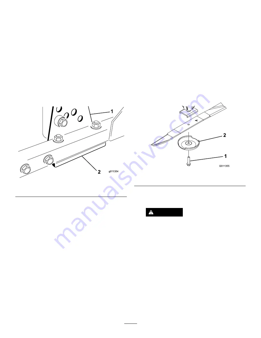
2.
Grasp the end of the blade using a rag or thickly-padded
glove. Remove the blade bolt, anti-scalp cup, and blade
from the spindle shaft (
).
G01 1355
1
2
Figure 65
1.
Blade bolt
2.
Anti-scalp cup
3.
Install the blade, sail facing toward the cutting unit,
with the anti-scalp cup and blade bolt (
Tighten the blade bolt to 115–149 N-m (85–110 ft-lb).
DANGER
A worn or damaged blade can break, and a
piece of the blade could be thrown into the
operator’s or bystander’s area, resulting in
serious personal injury or death
•
Inspect the blade periodically for wear or
damage.
•
Never weld a broken or cracked blade.
•
Always replace a worn or damaged blade.
Inspecting and Sharpening the Blade
1.
Raise the cutting unit to the highest position, shut the
engine off, and engage the parking brake.
Note:
Block the cutting unit to prevent it from falling
accidentally.
2.
Examine the cutting ends of the blade carefully,
especially where the flat and curved parts of the blade
46
Summary of Contents for 30809 Groundsmaster 3500-G
Page 10: ...121 3533 1 Read the Operator s Manual for information on maintenance 10...
Page 50: ...Notes 50...
Page 51: ...Notes 51...


