background image

3

Introduction

Read this manual carefully to learn how to operate and
maintain your product properly. The information in this
manual can help you and others avoid injury and product
damage. Although Toro designs and produces safe
products, you are responsible for operating the product
properly and safely.

Whenever you need service, genuine Toro parts, or
additional information, contact an Authorized Service
Dealer or Toro Customer Service and have the model and
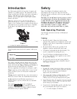
serial numbers of your product ready. Figure 1 illustrates
the location of the model and serial numbers on the
product.

1

m–5191

Figure 1

1.

Location of the model and serial numbers

Write the product model and serial numbers in the space
below:

Model No.

Serial No.

This manual identifies potential hazards and has special
safety messages that help you and others avoid personal
injury and even death. DangerWarning, and Caution are
signal words used to identify the level of hazard.
However, regardless of the hazard, be extremely careful.

Danger signals an extreme hazard that will cause serious
injury or death if you do not follow the recommended
precautions.

Warning signals a hazard that may cause serious injury or
death if you do not follow the recommended precautions.

Caution signals a hazard that may cause minor or
moderate injury if you do not follow the recommended
precautions.

This manual uses two other words to highlight
information. 

Important

 calls attention to special

mechanical information and Note: emphasizes general
information worthy of special attention.

Safety

Note: The addition of attachments made by other
manufacturers that do not meet American National
Standards Institute certification will cause noncompliance
of this machine.

Improper use or maintenance by the operator or owner
can result in injury. To reduce the potential for injury,
comply with these safety instructions and always pay
attention to the safety alert 

 symbol, which means

CAUTION, WARNING, or DANGER—“personal
safety instruction.” Failure to comply with the
instruction may result in personal injury or death.

Safe Operating Practices

The following instructions are from ANSI standard
B71.4—1999.

Training

Read the Operator’s Manual and other training
material. If the operator(s) or mechanic(s) can not read
English it is the owner’s responsibility to explain this
material to them.

Become familiar with the safe operation of the
equipment, operator controls, and safety signs.

All operators and mechanics should be trained. The
owner is responsible for training the users.

Never let children or untrained people operate or
service the equipment. Local regulations may restrict
the age of the operator.

The owner/user can prevent and is responsible for
accidents or injuries occurring to himself or herself,
other people or property.

Preparation

Evaluate the terrain to determine what accessories and
attachments are needed to properly and safely perform
the job. Only use accessories and attachments
approved by the manufacturer.

Wear appropriate clothing including hard hat, safety
glasses and hearing protection. Long hair, loose
clothing or jewelry may get tangled in moving parts.

Inspect the area where the equipment is to be used and
remove all objects such as rocks, toys and wire which
can be thrown by the machine.

Use extra care when handling gasoline and other fuels.
They are flammable and vapors are explosive.

Use only an approved container

Summary of Contents for 30321

Page 1: ...Operator s Manual Domestic English EN Form No 3327 382 Mid Size Mower ProLine T Bar Gear 17 HP with 44 in Side Discharge Mower Model No 30321 Serial No 230000001 and Up...

Page 2: ...e Handle Assembly 13 Installing the Shift Lever Plate and Fuel Tank 13 Adjusting the Shift Lever Plate 14 Installing the Control Rods 15 Page Installing the Hairpin Cotter Pins and Washers 16 Operatio...

Page 3: ...cturers that do not meet American National Standards Institute certification will cause noncompliance of this machine Improper use or maintenance by the operator or owner can result in injury To reduc...

Page 4: ...eet away from the cutting unit Look behind and down before backing up to be sure of a clear path Keep pets and bystanders away Slow down and use caution when making turns and crossing roads and sidewa...

Page 5: ...l slopes and ramps require extra caution If you feel uneasy on a slope do not mow it DO Remove obstacles such as rocks tree limbs etc from the mowing area Watch for holes ruts or bumps Tall grass can...

Page 6: ...6 Slope Chart...

Page 7: ...7...

Page 8: ...Safety decals and instructions are easily visible to the operator and are located near any area of potential danger Replace any decal that is damaged or lost 43 8480 52 2010 66 1340 67 5360 68 8340 8...

Page 9: ...9 98 0776 98 4387 1 Warning wearhearing protection 104 8186 104 8569 106 5532 106 0699 105 0884 106 0635...

Page 10: ...10 106 5494 106 5499 1 Engine stop 2 Engine start 3 Move the control bar to the handle then pull the knob 106 5505...

Page 11: ...possible then refuel such equipment on a truck or trailer from a portable container rather than from a gasoline dispenser nozzle If a gasoline dispenser nozzle must be used keep the nozzle in contact...

Page 12: ...e Bolt 5 16 x 7 8 inch Lock washer 5 16 inch Washer 5 16 inch Spring Hose clamp 1 1 2 2 4 2 1 Installing shift lever plate and fuel tank 3 No parts needed Adjusting the shift lever plate 4 Clevis pin...

Page 13: ...e Handle assembly must be installed before fuel tank is installed 2 Step Parts needed for this step 1 Fuel tank with studs installed 1 Shift lever plate 2 Bolts 5 16 x 7 8 inch 2 Lock washers 5 16 inc...

Page 14: ...for this step Adjusting the Shift Lever Plate 1 Shift lever to second gear and check alignment of lever in slot of shifter lever plate The clearance between top and bottom of the shift lever should b...

Page 15: ...fitting 2 3 1 2inch 89 mm 3 Idler bracket 4 Clevis pin washer and hairpin cotter 5 Rod fitting 6 Hole F 3 Check the gap between upper control bar and fixed bar with wheel drive fully engaged Gap shou...

Page 16: ...ake lever 3 Fixed bar 5 Step Parts needed for this step 2 Hairpin cotter pins Installing the Hairpin Cotter Pins and Washers Unused height of cut spacers may be stored on posts and retained by a hairp...

Page 17: ...on with control bail to release clutch brake and engage clutch to drive mower blades Gear Shift Lever Transmission has five forward speeds neutral and reverse and has an in line shift pattern Importan...

Page 18: ...start a warm engine move throttle control to the fast position 4 Grasp recoil starter handle firmly and pull out until positive engagement results then pull handle vigorously to start engine and allow...

Page 19: ...h time Note If the safety system does not operate as described below have an Authorized Service Dealer repair the safety system immediately 1 Set the parking brake and start the engine refer to Starti...

Page 20: ...ine until drive wheels contact curb Fig 18 6 Lower the front of the machine Fig 18 Note Both drive wheels should contact the curb and caster wheels straight 7 At the same time engage lower control bar...

Page 21: ...he mower because the grass deflector routes material down toward the turf If the grass deflector is ever damaged replace it immediately Never put your hands or feet under the mower Never try to clear...

Page 22: ...The handle position can be adjusted to match the operator s height preference 1 Remove hairpin cotter washer and clevis pin securing control rod fitting to idler bracket Fig 22 1 3 2 4 4 5 6 m 5316 Fi...

Page 23: ...Mid Size Weight Kit A weight kit is available for this machine This kit is optional and can be obtain from an Authorized Service Dealer The weight kit mounted in the front position is required when a...

Page 24: ...eck Electric Clutch adjust Engine clean outside 200 Hours Fuel Filter replace Oil Filter change 200 hours or every other oil change Paper Air Cleaner replace 250 Hours Transmission Couplings grease1 4...

Page 25: ...the foam element in liquid soap and warm water When the element is clean rinse it thoroughly 2 Dry the element by squeezing it in a clean cloth 3 Put one or two ounces of oil on the element Fig 26 Sq...

Page 26: ...ck fully onto the filler tube Fig 28 Pull the dipstick out and look at the metal end If oil level is low slowly pour only enough oil into the filler tube to raise the level to the full mark Important...

Page 27: ...kcase with the proper type of new oil refer to Engine Oil Service page 26 Servicing the Spark Plug Service Interval and Specification Check the spark plug s after every 100 operating hours Make sure t...

Page 28: ...and wait for all moving parts to stop before leaving the operating position 3 Clean the grease fittings with a rag Make sure to scrape any paint off the front of the fitting s 4 Connect a grease gun...

Page 29: ...e Interval Specification Maintain the air pressure in the front and rear tires as specified Check the pressure at the valve stem after every 40 operating hours or monthly whichever occurs first Fig 36...

Page 30: ...age 18 5 To adjust the brake remove the hair pin cotter and washer from the brake lever and trunnion Fig 38 6 Rotate the wing nut clockwise to increase the braking pressure 7 Rotate the wing nut count...

Page 31: ...fuel line off the valve Fig 40 Open fuel shut off valve and allow gasoline to drain into a gas can or drain pan Note Now is the best time to install a new fuel filter because the fuel tank is empty R...

Page 32: ...k plug s Inspecting the Blades 1 Inspect the cutting edges Fig 42 If the edges are not sharp or have nicks remove and sharpen the blades Refer to Sharpening the Blades on page 33 2 Inspect the blades...

Page 33: ...nt of material is removed from both cutting edges 1 m 1854 Figure 46 1 Sharpen at original angle 2 Check the balance of the blade by putting it on a blade balancer Fig 47 If the blade stays in a horiz...

Page 34: ...A 1 5 16 inch 33 mm 1 4 inch 6 mm 5 Straight edge 6 Carrier frame cross tube Checking Engine Deck Height 1 Disengage the PTO and set the parking brake 2 Stop the engine remove the key and wait for al...

Page 35: ...cations A and B 5 Caster spacers Checking the Deck Front to Rear Pitch 1 Check the tire pressure on both deck and traction unit 2 Position one blade front to rear Fig 52 Measure at C and D locations F...

Page 36: ...h 6 mm A Front B m 1078 Figure 55 MEASURE FROM CUTTING EDGE TO A LEVEL SURFACE m 2550 Figure 56 Changing the Side to Side Leveling Changing the side to side leveling is done by adjusting tire pressure...

Page 37: ...e Fig 59 6 Tighten the bottom two mounting screws enough to allow the belt to pass between the drive pulley and idler support Fig 59 2 m 1722 1 4 3 5 Figure 59 1 Top capscrew 2 Idler bracket 3 Idler s...

Page 38: ...ting unit then reinstall and tighten the knobs 11 Install the carrier frame cover and rubber washers onto the cutting unit then install and tighten the hand knobs 4 3 1 5 3 2 6 m 6529 Figure 61 1 Deck...

Page 39: ...rect installation and to maintain a level deck 4 2 1 3 2 m 6372 Figure 63 1 Locking Pin 2 Spacers locate as required 3 Carrier frame mounting tube 4 Caster wheel fork 4 Insert a pin punch into the mou...

Page 40: ...the wheel bolt and locknut Tighten the locknut until the spanner bushing bottoms against the inside of the caster forks Fig 65 7 Grease the fitting on the caster wheel Replacing the Grass Deflector A...

Page 41: ...D1 D4 C2 D6 HOUR METER OPTIONAL PK W AC AC IGNITION MODULE REG MAG SPARK PLUG PK 7 5A F1 S2 CLUTCH SW MOMENTARY PK G KEY SW S3 BAIL SW NORMALLY OPEN BN OR PK KEY SWITCH NONE G M OFF ON M S1 IGNITION W...

Page 42: ...to distribute conditioned fuel through the fuel system 5 minutes B Stop engine allow to cool and drain the fuel tank refer to Fuel Tank page 31 or operate engine until it stops C Restart engine and r...

Page 43: ...2 Clean air cleaner element 3 Oil level in crankcase is low 3 Add oil to crankcase 4 Cooling fins and air passages under engine blower housing are plugged 4 Remove obstruction from cooling fins and ai...

Page 44: ...blade s is are bent 2 Install new cutting blade s 3 Mower is not level 3 Level mower from side to side and front to rear 4 Underside of mower is dirty 4 Clean the underside of the mower 5 Tire pressur...

Page 45: ......

Page 46: ......

Page 47: ......

Page 48: ...ered There is no other express warranty except for special emission system coverage on some products This express warranty does not cover the following Cost of regular maintenance service or parts suc...

Reviews: