


2
All Rights Reserved
Printed in the USA
2003 by The Toro Company
8111 Lyndale Avenue South
Bloomington, MN 55420-1196
CALIFORNIA
Proposition 65 Warning
The engine exhaust from this product contains
chemicals known to the State of California to
cause cancer, birth defects, or other reproductive
harm.
Warning
Important
This engine is not equipped with a spark
arrester muffler. It is a violation of California Public
Resource Code Section 4442 to use or operate this engine
on any forest–covered, brush–covered or grass–covered
land. Other states or federal areas may have similar laws.
This spark ignition system complies with Canadian
ICES-002.
Ce système d’allumage par étincelle de véhicule est
conforme à la norme NMB-002 du Canada.
The enclosed Engine Owner’s Manual is supplied for
information regarding The U.S. Environmental
Protection Agency (EPA) and the California Emission
Control Regulation of emission systems, maintenance
and warranty.
Keep this engine Owner’s Manual with your unit.
Should this engine Owner’s Manual become damaged
or illegible, replace immediately. Replacements may be
ordered through the engine manufacturer.
Contents
Page
Contents
2
. . . . . . . . . . . . . . . . . . . . . . . . . . . . . . . . . . .
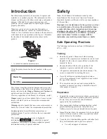
Introduction
3
. . . . . . . . . . . . . . . . . . . . . . . . . . . . . . . .
Safety
3
. . . . . . . . . . . . . . . . . . . . . . . . . . . . . . . . . . . . .
Safe Operating Practices
3
. . . . . . . . . . . . . . . . . . .
Toro Mower Safety
4
. . . . . . . . . . . . . . . . . . . . . . .
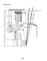
Slope Chart
6
. . . . . . . . . . . . . . . . . . . . . . . . . . . . . .
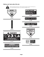
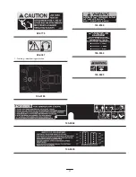
Safety and Instruction Decals
8
. . . . . . . . . . . . . . .
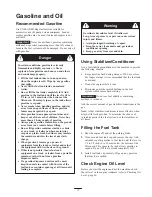
Gasoline and Oil
11
. . . . . . . . . . . . . . . . . . . . . . . . . . . .
Recommended Gasoline
11
. . . . . . . . . . . . . . . . . . .
Using Stabilizer/Conditioner
11
. . . . . . . . . . . . . . . .
Filling the Fuel Tank
11
. . . . . . . . . . . . . . . . . . . . . .
Check Engine Oil Level
11
. . . . . . . . . . . . . . . . . . . .
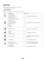
Set Up
12
. . . . . . . . . . . . . . . . . . . . . . . . . . . . . . . . . . . .
Loose Parts
12
. . . . . . . . . . . . . . . . . . . . . . . . . . . . . .
Installing the Handle Assembly
13
. . . . . . . . . . . . . .
Installing the Shift Lever Plate and Fuel Tank
13
. .
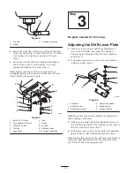
Adjusting the Shift Lever Plate
14
. . . . . . . . . . . . . .
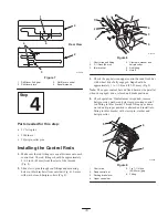
Installing the Control Rods
15
. . . . . . . . . . . . . . . . .
Page
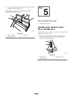
Installing the Hairpin Cotter Pins and Washers
16
. .
Operation
17
. . . . . . . . . . . . . . . . . . . . . . . . . . . . . . . . . .
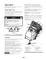
Think Safety First
17
. . . . . . . . . . . . . . . . . . . . . . . .
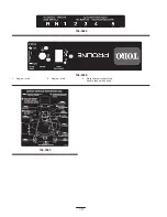
Controls
17
. . . . . . . . . . . . . . . . . . . . . . . . . . . . . . . .
Using the Parking Brake
18
. . . . . . . . . . . . . . . . . . .
Starting and Stopping the Engine
18
. . . . . . . . . . . .
Operating the Mower Blade Control (PTO)
18
. . . .
The Safety Interlock System
19
. . . . . . . . . . . . . . . .
Driving Forward or Backward
19
. . . . . . . . . . . . . . .
Using the Lower Control Bar Operation
20
. . . . . . .
Stopping the Machine
20
. . . . . . . . . . . . . . . . . . . . .
Transporting Machines
21
. . . . . . . . . . . . . . . . . . . .
Side Discharge or Mulch Grass
21
. . . . . . . . . . . . . .
Adjusting the Height-of-Cut
21
. . . . . . . . . . . . . . . .
Adjusting the Gage Wheels
22
. . . . . . . . . . . . . . . . .
Adjusting the Handle Height
22
. . . . . . . . . . . . . . . .
Using the Mid–Size Weight Kit
23
. . . . . . . . . . . . . .
Maintenance
24
. . . . . . . . . . . . . . . . . . . . . . . . . . . . . . . .
Recommended Maintenance Schedule
24
. . . . . . . .
Servicing the Air Cleaner
25
. . . . . . . . . . . . . . . . . .
Servicing the Engine Oil
26
. . . . . . . . . . . . . . . . . . .
Servicing the Spark Plug
27
. . . . . . . . . . . . . . . . . . .
Greasing and Lubrication
28
. . . . . . . . . . . . . . . . . . .
Cleaning the Cooling System
29
. . . . . . . . . . . . . . .
Checking the Tire Pressure
29
. . . . . . . . . . . . . . . . .
Servicing the Fuse
29
. . . . . . . . . . . . . . . . . . . . . . . .
Servicing the Brakes
29
. . . . . . . . . . . . . . . . . . . . . .
Adjusting the Electric Clutch
30
. . . . . . . . . . . . . . .
Servicing the Fuel Tank
31
. . . . . . . . . . . . . . . . . . . .
Servicing the Fuel Filter
31
. . . . . . . . . . . . . . . . . . .
Servicing the Cutting Blades
32
. . . . . . . . . . . . . . . .
Correcting the Mower Quality of Cut
33
. . . . . . . . .
Frame Set Up
34
. . . . . . . . . . . . . . . . . . . . . . . . . . . .
Checking the Deck Front-to-Rear Pitch
35
. . . . . . .
Changing the Deck Front-to-Rear Pitch
35
. . . . . . .
Checking the Deck Side-to-Side Leveling
36
. . . . .
Changing the Side-to-Side Leveling
36
. . . . . . . . . .
Matching Height of Cut
36
. . . . . . . . . . . . . . . . . . . .
Replacing the Traction Drive Belt
37
. . . . . . . . . . . .
Replacing the Transmission Belt
37
. . . . . . . . . . . . .
Replacing the Mower Belt
38
. . . . . . . . . . . . . . . . . .
Replacing the PTO Drive Belt
38
. . . . . . . . . . . . . . .
Replacing the Caster Wheel Fork Bushings
39
. . . .
Caster Wheel and Bearings Service
40
. . . . . . . . . . .
Replacing the Grass Deflector
40
. . . . . . . . . . . . . . .
Wiring Diagram
41
. . . . . . . . . . . . . . . . . . . . . . . . . .
Cleaning and Storage
42
. . . . . . . . . . . . . . . . . . . . . .
Troubleshooting
43
. . . . . . . . . . . . . . . . . . . . . . . . . . . . .
The Toro Total Coverage Guarantee
48
. . . . . . . . . . . . .