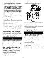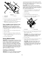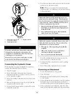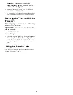
Figure 39 illustrates the fuse block and identifies the
fuse positions.
Figure 39
1.
30 amp. fuse—main
circuit
3.
10 amp fuse—control
panel/relay
2.
Empty
4.
Open position for optional
accessories
Note:
If the traction unit will not start, either the main
circuit or control panel/relay fuse could be blown.
To access the fuses, you must remove the fuse panel,
as follows:
1. Stop the engine and remove the key.
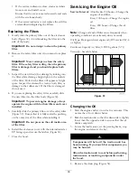
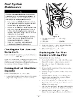
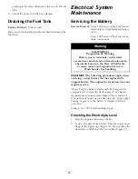
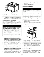
2. Raise the hood.
3. Pull the hairpin cotter from the bottom end of the
hood prop-rod and slide the prop rod out of the
retaining brackets and the prop-rod tab (Figure 40).
Figure 40
1.
Prop-rod tab
4.
Retaining
bracket—bottom
2.
Retaining bracket—top
5.
Hairpin cotter
3.
Prop-rod
4. Remove the 4 screws securing the fuse panel
and then pull the panel out and up to remove it
(Figure 41).
Figure 41
1.
Fuse panel
2.
Screw
5. Check the fuses.
6. Install the fuse panel using the 4 screws removed
previously.
7. Install the prop-rod into the retaining brackets and
prop-rod tab and secure it with the hairpin cotter
(Figure 40).
8. Close the hood.
35
Summary of Contents for 22319
Page 7: ...Slope Indicator 7...
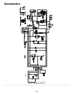
Page 49: ...Schematics G007388 Electrical Schematic Rev B 49...
Page 50: ...Hydraulic Schematic Rev A 50...
Page 51: ...Notes 51...


