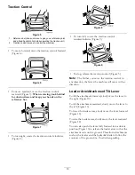
Traction Control
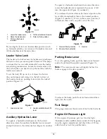
Figure 5
1.
Reference bar (does not move to give you a reference point
and a fixed handle to hold while operating the traction unit)
2.
Traction control (moves to control the machine)
•
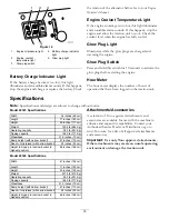
To move forward, move the traction control forward
(Figure 6).
Figure 6
•
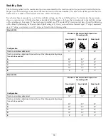
To move rearward, move the traction control
rearward (Figure 7).
When reversing, look behind
for obstructions and keep your hands on the
reference bar.
Figure 7
•
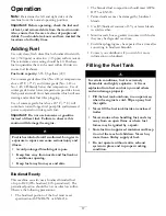
To turn right, rotate the traction control clockwise
(Figure 8).
G008131
Figure 8
•
To turn left, rotate the traction control
counterclockwise (Figure 9).
G008132
Figure 9
•
To stop, release the traction control (Figure 5).
Note:
The farther you move the traction control in
any direction, the faster the machine will move in that
direction.
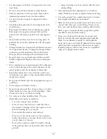
Loader Arm/Attachment Tilt Lever
To tilt the attachment forward, slowly move the lever to
the right (Figure 10).
To tilt the attachment rearward, slowly move the lever to
the left (Figure 10).
To lower the loader arms, slowly move the lever forward
(Figure 10).
To raise the loader arms, slowly move the lever rearward
(Figure 10).
You can also push the lever fully forward into a detent
position (Figure 10) to release the loader arms so that the
attachment rests on the ground. This allows attachments
such as the leveler and the hydraulic blade to follow the
contours of the ground (i.e., float) when grading.
13
Summary of Contents for 22319
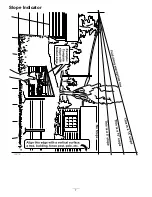
Page 7: ...Slope Indicator 7...
Page 49: ...Schematics G007388 Electrical Schematic Rev B 49...
Page 50: ...Hydraulic Schematic Rev A 50...
Page 51: ...Notes 51...


