


Installation Instructions
3
1
3
2
4
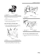
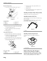
Figure 2
1.
Fuel line clamp
2.
Fuel line
3.
Tank bracket
4.
Fuel tank
2. Remove the fuel tank from the tank bracket
(Fig. 2).
3. Remove the tank bracket.
4. Install two screws and two locknuts to fill the holes
left from removing the tank bracket.
Disconnecting the Throttle Cable
1. Remove two self-tapping screws that secure the belt
cover to the lawn mower deck (Fig. 3). Set the cover
and the fasteners aside for the installation.
m-224
2
1
2
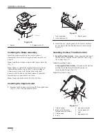
Figure 3
1.
Belt cover
2.
Self-tapping screw (2)
2. Loosen the cable clamp screw and disconnect the
throttle cable from the throttle lever (Fig. 4 or Fig. 5).
m-286
2
3
1
Figure 4
1.
Cable clamp screw
2.
Throttle cable
3.
Throttle lever
1
2
3
4
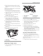
Figure 5
1.
Cable clamp screw
2.
Cable clamp
3.
Throttle cable
4.
Throttle arm
Disconnecting the Blade Brake Cable
1. Disconnect the blade brake cable from the brake arm
(Fig. 6).


