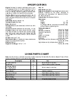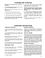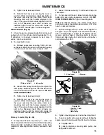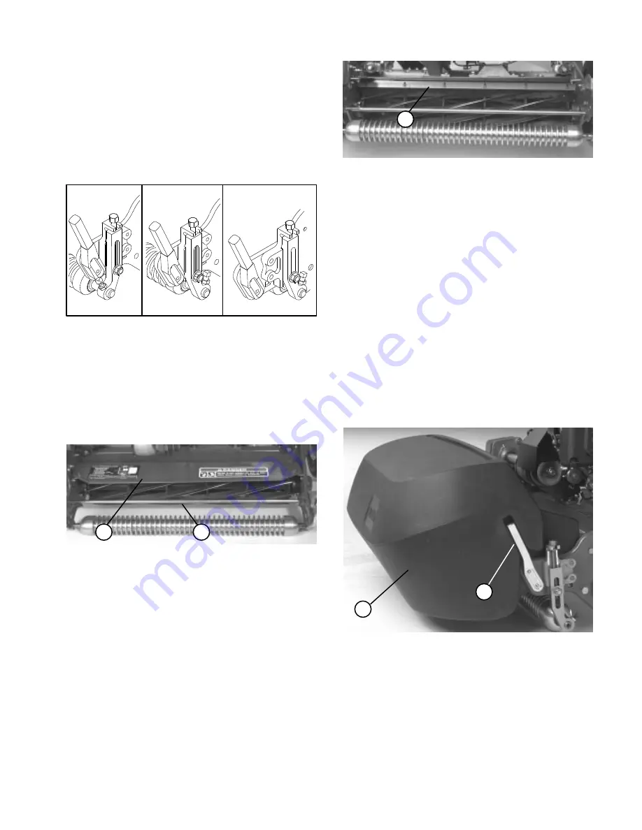
The front roller can be put in three different
positions (Fig. 14) depending on the application and
needs of the user.
D
The front position is used when a groomer is
installed.
D
The middle position is used without a groomer.
D
The third position can be used in extremely
undulating turf conditions.
'%0-#
Adjust shield to assure proper grass clipping
discharge into basket.
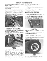
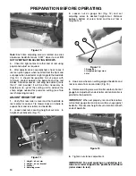
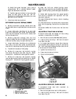
. Measure distance from top of front support rod to
the front lip of the shield at each end of cutting unit
(Fig. 15).
'%0-#
0,,+-/ +"
&'#)"
Height of shield from support rod for normal cutting
conditions should be 4 inches. Loosen capscrews and
nuts securing each end of shield to sideplate, adjust
shield to correct height and tighten fasteners.
+/#
Shield can be lowered for drier conditions
(clippings fly over top of basket) or raised to allow for
heavy wet grass conditions (clippings build up on rear
of basket).
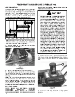
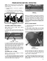
Adjust cut-off bar to assure clippings are cleanly
discharged from the reel area:
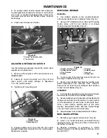
Loosen screws securing top bar (Fig. 16) to cutting
unit. Insert .060 inch feeler gauge between top of reel
and bar and tighten screws. Assure bar and reel are
equal distance apart across complete reel.
'%0-#
0/+$$ ! -
+/#
Bar is adjustable to compensate for changes in
turf conditions. Bar should be adjusted closer to reel
when turf is extremely wet. By contrast, adjust bar
further away from reel when turf conditions are dry. Bar
should be parallel to reel to assure optimum
performance and should be adjusted whenever shield
height is adjusted or whenever reel is sharpened on a
reel grinder.
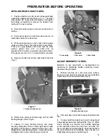
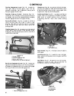
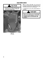
Grasp basket by top lip and slide onto the basket
mounting rods (Fig. 17).
When cutting in higher height-of-cuts, basket
may be lowered by removing each basket mounting
rod and re-installing on opposite side of machine.
'%0-#
- .. ! .(#/
.(#/ +0*/'*% +"
Place traction lever into ENGAGE position and
engine controls in starting position.
Attempt to start engine. Engine should not start. If
engine starts, the interlock switch needs service.
Correct problem before operating. Refer to Adjusting
Interlock Switch.


