


Height-of-Cut Chart
HOC Setting
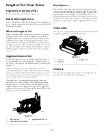
Aggressiveness of Cut
No. of Rear Spacers
No. of Chain Links
With Groomer kits
installed**
0.64 cm (0.250 inches)
Less
Normal
More
0
0
1
3+
3+
3
Y
Y
-
0.95 cm (0.375 inches )
Less
Normal
More
0
1
2
4
3
3
Y
Y
-
1.27 cm (0.500 inches)
Less
Normal
More
0
1
2
4
3+
3
Y
Y
Y
1.56 cm (0.625 inches)
Less
Normal
More
1
2
3
4
3
3
Y
Y
-
1.91 cm (0.750 inches)
Less
Normal
More
2
3
4
3+
3
3
Y
Y
-
2.22 cm (0.875 inches)
Less
Normal
More
2
3
4
4
3
3
Y
Y
-
2.54 cm (1.000 inch)
Less
Normal
More
3
4
5
3+
3
3
Y
Y
-
2.86 cm (1.125 inches)*
Less
Normal
More
4
5
6
4
3
3
-
-
-
3.18 cm (1.250 inches)*
Less
Normal
More
4
5
6
4
3
3
-
-
-
3.49 cm (1.375 inches)*
Less
Normal
More
4
5
6
4
3
3
-
-
-
3.81 cm (1.500 inches)*
Less
Normal
More
5
6
7
3+
3
3
-
-
-
+ Indicates the U-bracket, on lift arm, is positioned in the bottom hole (
).
* High HOC Kit (Part 110-9600) must be installed. The front HOC bracket must be positioned in the top side-plate hole.
** Y indicates that this combination of HOC and spacers can be used with groomers.
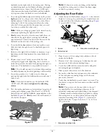
Note:
Changing 1 chain link changes the rear roller pitch angle movement by 7.0 degrees.
Note:
Changing the U-bracket, on the lift arm, to the bottom hole adds 3.5 degrees to the rear roller pitch angle.
10
Summary of Contents for 03621
Page 20: ...Notes 20 ...
Page 21: ...Notes 21 ...