background image

3.  OPERATING INSTRUCTIONS

T-OMPBM  12/2020

8

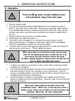
A. Initial Assembly

1. Remove all contents from box and ensure all components are present per the 

BOX CONTENTS section of this manual

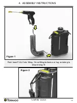
2. Firmly attach one end of hose to the wand assembly and the other end to the 

machine ensuring the hose is fully inserted (Fig 1).

3. Attach the shoulder strap to the unit.  The mister can be used with the carrying 

handle or the shoulder strap (Fig 2).

B. Battery Charging

1. Remove battery and battery charger from individual boxes.

2.

Plug charger AC cable into 115V wall socket and insert battery into charger.  

Battery was designed to fit into charger only one way to ensure alignment of 

charging ports.

3. If the battery needs charging, the light on the charger will turn red.  When 

charging is complete, the red light will turn green.  Flashing green light indicates 

charger is in stand-by mode.

C. Battery Installation

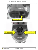
1. Once the battery is fully charged, insert battery in the port located underneath 

the main unit (Fig 3). 

2. Insert battery into port and push until tabs engage.  Battery will only insert into 

port one way.

3. To remove battery, simultaneously depress tabs on side of battery and pull out 

(Fig 4).

4. Charge as required.

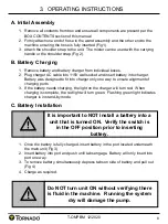
It is important to NOT install a battery into a 

unit that is turned ON.  Verify the switch is 

in the OFF position prior to inserting 

battery.

Do NOT turn unit ON without verifying there 

is fluid in the machine.  Running the system 

dry will damage the pump.

Summary of Contents for TP200-Q02-U

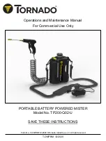
Page 1: ...ns and Maintenance Manual For Commercial Use Only PORTABLE BATTERY POWERED MISTER Model No TP200 Q02 U SAVE THESE INSTRUCTIONS T OMPBM 12 2020 Form No T OMPBM 12 2020 Tornado Industries LLC All right...

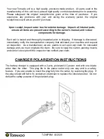
Page 2: ...nspected prior to shipping If damage is discovered immediately notify the transportation company that delivered your machine and request an inspection As a manufacturer we are unable to act upon any c...

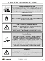
Page 3: ...of screws and accessing internal components will void all warranty claims Personal Protection Equipment PPE should be worn during the operation of this machine Chemicals can remain airborne for some...

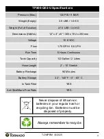
Page 4: ...mm Voltage 10 8 VDC Flow 1 75 GPH 6 6 LPH Run Time 6 Hours Continuous Tank Capacity 1 2 Gallon 2 Liters Hose Length 2 10 Stretch Battery Recharge 90 Minutes Battery Storage 32 140 F 0 60 C In Tank Fi...

Page 5: ...11 To ensure disinfection follow chemical manufacturer s recommendation of dwell time how long the disinfectant sits on a surface prior to removal Dispose of wipe down towel properly or allow disinfec...

Page 6: ...ls known to the state of California to cause birth defects or other reproductive harm Chemical Warning Straight bleach should never be used solely in this unit When sodium hypochlorite a component fou...

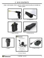
Page 7: ...T OMPBM 12 2020 7 Upon initial receipt of unit open box and ensure all parts are included as shown below 1 Wand Assembly 2 Coiled Hose 3 Mister Assembly 6 Owner s Manual 4 Strap Assembly 5 Battery 7 B...

Page 8: ...only one way to ensure alignment of charging ports 3 If the battery needs charging the light on the charger will turn red When charging is complete the red light will turn green Flashing green light i...

Page 9: ...r release to keep pressure on the system This will repeat during use Read and understand the requirements of the disinfectant used Dwell time or the amount of time a solution must remain on a surface...

Page 10: ...age Battery not fully installed Clogged tip Low fluid level Charge battery Ensure battery fully installed Clean tip Fill tank Machine will not turn on Low battery voltage Defective Switch Pump Failure...

Page 11: ...ve all pressure from system 3 Pull black plastic towards wand while pulling coiled hose out of fitting 2 Pull Hose Down 1 Pull Black Plastic Up to Release Hose 4 Point free end of hose into approved c...

Page 12: ...4 ASSEMBLY INSTRUCTIONS T OMPBM 12 2020 12 Figure 1 Push hose FULLY into fitting Once fitting bottoms out tug on tubing to ensure snug fit Figure 2...

Page 13: ...5 BATTERY INSTALLATION T OMPBM 12 2020 13 Figure 3 Battery Port Press on both sides at the same time Figure 4 To remove battery...

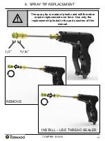
Page 14: ...PBM 12 2020 14 Figure 3 Figure 4 The spray tip is made of plastic and will therefore require replacement over time Use only the replacement tip listed in the parts section of this manual 9 16 1 2 REMO...

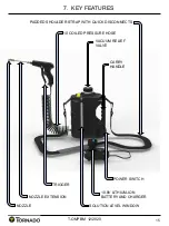
Page 15: ...BM 12 2020 15 PADDED SHOULDER STRAP WITH QUICK DISCONNECTS 10 8V LITHIUM ION BATTERY AND CHARGER 10 COILED PRESSURE HOSE VACUUM RELIEF VALVE POWER SWITCH CARRY HANDLE NOZZLE EXTENSION NOZZLE TRIGGER S...

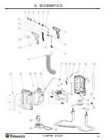
Page 16: ...8 SCHEMATICS T OMPBM 12 2020 16 Figure 3...

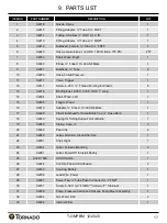
Page 17: ...1 Long 1 14 X2204 Shell Wand Left 1 15 X2205 Trigger Wand 1 16 X2219 Adapter Tube X 10 32 UNF Male 1 17 X2226 Plastic Bulkhead for Small Bottle Cap Hose Barb 1 18 X2249 Spring for Tubing Support Out...

Page 18: ...p Solution Bottle Aftermarket Part 1 35 X2202 Bottle Fluid Caps and Seals 1 36 X2200 Shell Left 1 37 A732 8414 Screw 8 18 HI LO 8 38 X2207 Battery Lithium Ion 10 8V 1 39 X2208 Charger Lithium Ion Batt...

Page 19: ...___________________ 4 ____________________________________________ 5 ____________________________________________ 6 ____________________________________________ 7 _____________________________________...

Page 20: ...12 2020 20 Figure 3 Tornado Industries LLC 3101 Wichita Court Ft Worth TX 76140 1755 Phone 800 VACUUMS Fax 1 817 551 0719 WWW TORNADOVAC COM Record of Purchase Serial Number Purchase Date Dealer Phone...

Reviews: