l
Position the motor so that its cord points down when the
motor is engaged. Depending on the operational position
(horizontal or vertical), you may have to reposition the motor
with respect to the motor mount.
l
Make sure that the paint is maintained on the motor body —
in particular, the magnetic laminations in the center.
l
Examine the oil view port for a milky fluid or raw coolant.
To remove coolant from the rotary table:
1. Drain the coolant from the rotary table.
2. Refill with one of the following:
l
AGMA 2 gear oil
l
SAE 30 weight motor oil
About the Rotary Table and Coolant
The rotary table is designed to operate in the presence of coolant,
but not when it's submersed in coolant. It's rarely a problem is
coolant is dripping over the edge. However, it is a problem if there's
a serious external coolant flow that submerses the joint between
the rotating table and the base casting.
The electric motor is sealed against cutting fluids. Do not allow the
following components to be subject to constant coolant flow or
high-pressure coolant jets:
l
Motor
l
Motor cable
l
The joint between the rotating table and the base casting
About the Rotary Table Lubrication System
There is an oil distribution system internal to the rotary table. As the
table turns, it carries oil over the worm gear.
Note:
The distribution system does not cover the sliding
joint between the rotating table and the base casting,
which is similar to the slideways of a mill and has a large,
flat surface supported by an oil film.
The oil port on the edge of the rotary table (and on the base casting
itself) provides oil to the sliding surfaces. It's important to
occasionally oil the ports to maintain an oil film, which is essential
to keep water and coolant away from the sliding joint. If you're
using coolant, and you do not oil the ports, coolant will enter the
rotary table.
Note:
Coolant contains anti-corrosion agents which protect
the table surfaces. A small amount of coolant and oil
generally forms an emulsion, which you can see as a milky
fluid inside the oil view port.
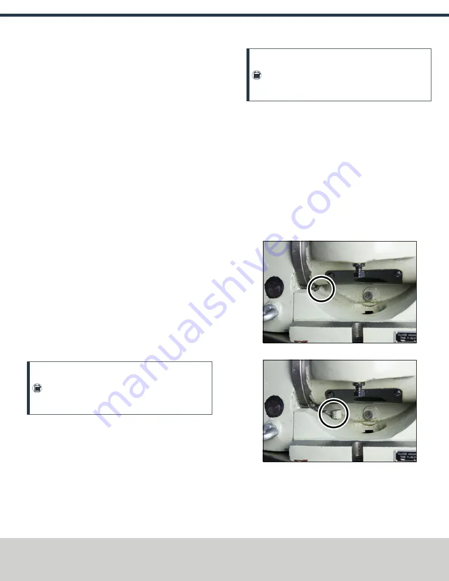
5.1.5 Examine the Locking Lugs
The 8-in. Tilting Rotary Table and 6-in. Tilting Rotary Table each
have two locking lugs. When they are moved out of position (either
intentionally or unintentionally), the rotary table will not tilt within
the full range of motion. The more interior locking lug is difficult to
realign with the recessed groove.
To manually align the interior locking lug:
1. Manually crank the handle and move the table to a position
that allows access to the displaced part.
2. Use your fingers (or a small tool) to move the locking lug back
into place. In its correct position, you should only see the cap
of the locking lug.
Figure 5-7: Example of the locking lug in the In position.
Figure 5-8: Example of the locking lug in the Out position.
5.1.6 Examine the Motor Coupling
If a motor coupling is loose or cracked, the table will slip relative to
motor rotation and, subsequently, lose position.
Page 11
©Tormach® 2019
Specifications subject to change without notice.
tormach.com
TD10552: Owner's Guide: 4th Axis (0919A)
TECHNICAL DOCUMENT


