TORCHVIEW CDVR-1608R User Manual Download Page 44

44 


4.4. PTZ Control 


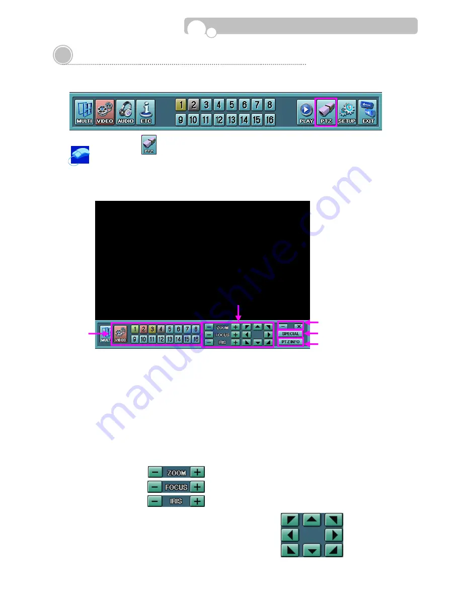
Control the Direction, Focus, Zoom, Iris of the connected PTZ camera. 


Click the PTZ       button to enter the PTZ control mode and click the mouse right button to 
make the PTZ Control Bar appear on the screen. 


PTZ control is possible only with cameras that support PTZ control, correct configurations must  

be made in [CAMERA SETUP] before it can be used. 


1

.


VIDEO Channel Selection 

• 

Select the channel(Cameral) by clicking on the channel buttons in the sub-menu bar or directly clicking 

on the screen of the relevant channel. 

• 

Selected channel button will be highlighted in green. 


2

.


PTZ Control 

• 

Pan, Tilt, Zoom, Focus, Iris Adjustment can be performed with these buttons. 

        ZOOM :   Use                     to Zoom-In and Zoom-Out. 

FOCUS :  Use                     to adjust Focus. 

IRIS   :   Use                     to adjust the Aperture. 

PAN/TILT :  Change the direction of the camera by using                      buttons.. 


Operation

Summary of Contents for CDVR-1608R

Page 1: ...User Manual Digital Video Recorder CDVR 1608R...

Page 2: ...is operated in a commercial environment This equipment generates uses and can radiate radio frequency energy and if not installed and used in accordance with the instruction manual may cause harmful...

Page 3: ...e operation of the product and to protect it from overheating and these openings must not be blocked or covered The openings should never be blocked by placing the product on a bed sofa rug or other s...

Page 4: ...heck Upon completion of any service or repairs to this product ask the service technician to perform safety checks to determine that the product is in proper operating condition 17 Heat The product sh...

Page 5: ...tup Information 3 10 Log List 3 11 Backup Format 4 OPERATION 4 1 Monitoring 4 1 1 Multi Screen Display 4 1 2 Changing Channel 4 1 3 Freeze Screen 4 1 4 Full Screen Display 4 2 Monitoring Control 4 2 1...

Page 6: ...components are damaged or missing do not attempt to use the unit contact the supplier immediately If the unit must be returned it must be shipped in the original packing box DVR Unit Remote Controlle...

Page 7: ...R Display the Monitoring Control Menu on the screen 7 PTZ Enter the PTZ control mode 8 SETUP Enter the Setup Mode 9 ESC Clear the Monitoring Control Menu Return to a higher Category Group Field Cancel...

Page 8: ...AOUT signals to monitor 5 AUDIO INPUT Connectors Input connectors for audio signals 6 VIDEO INPUT Connectors Input connectors for video signals 7 ALARM Output Terminal Connect the alarm devices in its...

Page 9: ...rlace RGB must be used Or TVs with RGB jack SONY monitors may be used after connecting RGB and HSYNC to the external SYNC Switch between TV VGA may be performed only during the Monitoring Mode 15 TERM...

Page 10: ...e during playback Fast reverse playback Playback in reverse forward direction Fast forward playback FULL SCR Change to full screen display during Search Playback in slow motion 1x 1 2x 1 4 1 8x 1 16 S...

Page 11: ...Hard Drives must be installed in the DVR according to the above order and adjust the Jumper Pin of the Hard Drive to the Master or Slave position Fasten 2 screws on each side of the HDD bracket to fi...

Page 12: ...ted has not been formatted recording will start after the formatting is completed Installation S M A R T Self Monitoring Analysis and Reporting Technology S M A R T is a reliability prediction technol...

Page 13: ...the cursor to the bottom of the screen to bring up the Menu bar on to the monitoring screen Click the mouse left button on the LOG OUT button on the right hand corner of the Menu Bar to escape from t...

Page 14: ...e installation will proceed automatically once the Firmware CD is inserted The CD will eject automatically once the installation is completed 4 Take out the CD and adjust the DIP Switch CD Switch to t...

Page 15: ...SWORD PTZ SETTING USER AUTHORITY ID COLOR SYSTEM NTSC PAL DRIVER S W VERSION BAUD RATE UPGRADE SETUP F W BMP DATA BIT FACTORY DEFAULT RESET PARITY STOP BIT NETWORK RECORD SCHEDULER IP TYPE RESOLUTION...

Page 16: ...DEO ADJUSTMENT FULL DISK PRE ALARM 5 RECORD FLICKER CANCEL SMART FAILURE CAMERA COLOR DIFFUSION DEVICE INFORMATION LAN VGA DE INTERLACE DEVICE BACKUP SPOT OUT SIZE SETUP SEQUENCE DWELL TIME TEMPERATUR...

Page 17: ...0 255 Use pop up Key Panel or turn the mouse wheel to change the number DATE TYPE YYYY MM DD Select DATE indication method YYYY MM DD MM DD YYYY DD MM YYYY Turn the mouse wheel to change the Date Typ...

Page 18: ...Switch in the DVR rear panel should be positioned to the Color System applicable in your region before turning on the DVR power S W VERSION Displays the installed Software version of the DVR UPGRADE I...

Page 19: ...Area by clicking on the desired areas in the view screen Designated area will be highlighted in blue Clicking on the ALL button will designate the entire area Clicking on the CLEAR button will clear a...

Page 20: ...A100L DOME1 DOME2 HSDN 251N WPT 101 SJ 2819 SK 2162D DSC 230 GROOM D106 CAZ1723 VC C4 SCC C4201 CRR1600T SRX 100B VVK 3000 ORX 1000 Baud Rate 300 115 200 Data Bit 7 8 Parity NONE ODD EVEN Stop Bit 1 2...

Page 21: ...mouse wheel to change the time TYPE NO Select the Sensor Type Please refer to the Sensor Manual to select the correct type Turn the mouse wheel to select between NO Normal Open and NC Normal Closed OP...

Page 22: ...168 123 98 Set the IP Address Input Range for each field 0 255 Use the pop up Key Panel or turn the mouse wheel to input the numbers GATEWAY 192 168 123 254 Set the Gateway Address Input Range for ea...

Page 23: ...mail address of the Receiver Max 50 characters can be used Use the pop up Key Panel to input characters PPPOE ID ADMIN Set the ID required for PPPOE networking Max 128 characters can be used Use the p...

Page 24: ...wheel to select the Resolution Type WATERMARK SETUP Digital encoding will be made on images for authentication Select whether to apply Watermark or not Watermark Strength and Key must also be set Clic...

Page 25: ...at 0 Input Range 0 30 for NTSC 0 25 for PAL Turn the mouse wheel or use the pop up Key Panel to change the FPS level QUALITY MIDDLE Set the Video Quality level Input Range LOW MIDDLE HIGH SUPER Turn...

Page 26: ...LUE FUNCTION OPERATION METHOD RECORDING CONDITION Select the Recording Condition for each Day and Time CONTINUOUS Green Record continuously MOTION Light Blue Start recording when motion is detected MO...

Page 27: ...e pop up Key Panel to change the dwell time FLICKER CANCEL YES Select this feature if the GUI becomes shaky when using composite output Turn the mouse wheel to select between YES NO COLOR DIFFUSION NT...

Page 28: ...ted to the designated person Click on the check box to enable disable FULL DISK PRE ALARM 5 Select the notification method when there remains only 5 HDD capacity BEEP Beeper in the DVR will be activat...

Page 29: ...t REC Log list of Recording Start Stop CAM Log list of Camera On Off LAN Log list of LAN connections BACKUP Log list of Backup executions SET Log list of Setup Configuration changes TIME Log list of S...

Page 30: ...e START button The selected storage device button will be highlighted in pink BACKUP Back up recorded data from the Hard Disk Drive to external storage Select the HDD and select the files to be copied...

Page 31: ...ge the multi screen display type 4 1 2 Changing Channel Changing the channel is possible only in 1 4 9 13 multi screen display modes In the 13 channel multi screen mode the channels in the center scre...

Page 32: ...lected to be viewed in Full Screen during multi screen monitoring Place the mouse cursor on the screen Channel and click the mouse left button In order to return to the previous multi screen monitorin...

Page 33: ...u 4 2 1 Multi Screen Display Full Screen and 4 9 13 16 Multi Screen Display types and Sequence Display can be selected from the Sub Menu of the Monitoring Control Bar In the 13 channel Multi Screen di...

Page 34: ...rding in progress GREEN Selected channel Click the VIDEO button and the channel buttons will appear in the sub menu Click the channel button you wish to see 4 2 3 Audio Displays the current status of...

Page 35: ...EXCELLENT The Status bar will disappear automatically after 10 seconds 2 Recording On Off Start Recording when not in recording mode or Stop Recording during record mode Recording will be performed ba...

Page 36: ...will be highlighted in pink When a Network connection occurs the icon will be highlighted in pink The Record icon will blink continuously if recording is in progress The Status Bar will pop up automa...

Page 37: ...button and select the search method from the Sub Menu Time Date Search Event Sensor Search File Search 4 3 1 Time Date Search Recorded video may be searched based on Time Date 1 Calendar Select the d...

Page 38: ...eo clip The scrollbar represents one hour and each scale mark represents 10 minutes Return to the beginning of the selected video clip during playback and playback will not resume unless otherwise ins...

Page 39: ...mage Fast reverse playback 2x 4x 8x 16x 32x Fast forward playback 2x 4x 8x 16x 32x Pause video during playback Paused video will resume playback at the speed it was being played if the button is re cl...

Page 40: ...range and the selected date will be highlighted in green Move to previous next month by clicking the buttons on the calendar Then click the relevant day 2 Sensor Channel Select a sensor channel or cha...

Page 41: ...the relevant day 2 Device Select the storage device Click on the storage device button Re clicking the button will enable disable the channel 3 File List Select a file you wish to view When searching...

Page 42: ...CDRW or the USB Memory Enter the Playback mode and search the image you wish to copy by using the playback buttons and click Then select the storage device from the pop up screen Approximately 5 seco...

Page 43: ...roll Bar 3 Click and mark the ending point of the video clip copy by clicking on the corresponding point in the Capture Scroll Bar 4 The memory capacity of the Video Clip and the available free capaci...

Page 44: ...be made in CAMERA SETUP before it can be used 1 VIDEO Channel Selection Select the channel Cameral by clicking on the channel buttons in the sub menu bar or directly clicking on the screen of the rele...

Page 45: ...e ex Lobby for the area the PTZ camera is directed Click on the field and use the pop up key panel to input the name 4 Designate the Sensor or Sensors that is to be linked to the PTZ camera The PTZ ca...

Page 46: ...s R Recording schedule has been set up Blinking R Actual recording is in progress Blinking M Motion detection recording is in progress Blinking S Sensor activated recording in progress PANIC RECORDING...

Page 47: ...00fps PAL Recording Mode Continuous Schedule Event Sensor Motion Detection Audio 8 Line In 1 Line Out Search Method Time Date Event Sensor Sensor Alarm 8 Alarm Input NO NC 8 Alarm Output PTZ Interface...

Page 48: ...not start even when there is motion adjust the camera sensitivity in CAMERA Setup Recorded data disappeared If the HDD capacity is full recording will continue by overwriting the oldest data To avoid...

Reviews: