


21
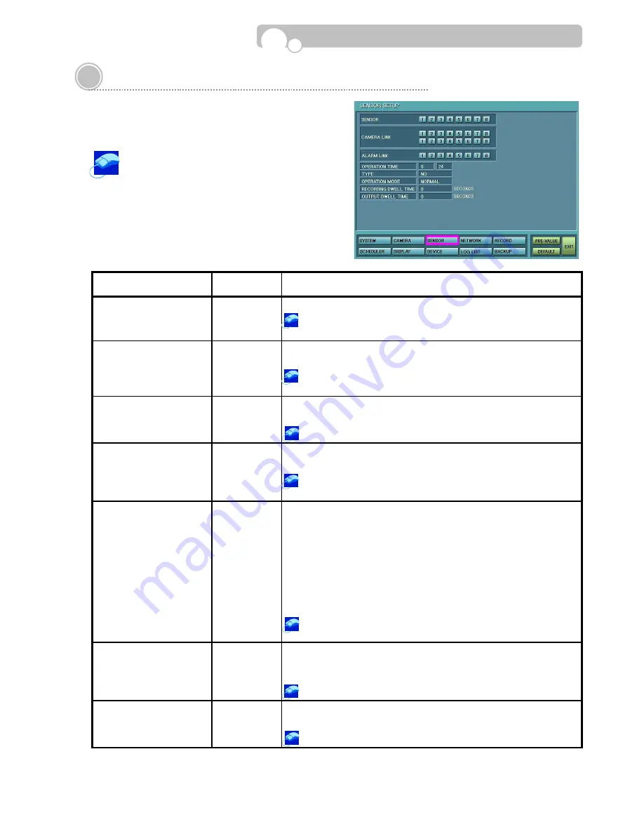
3.4. Sensor Setup
In Sensor Setup, you may designate Camera and Alarm
(Output) Link for each Sensors.
Select the Sensor from the Sensor numbers
displayed at the top of the screen and then
make the necessary linkage with the Camera and Alarm
(Output).
Save confirmation window will appear when changing to
a new Sensor number if setup values have be changed.
CATEGORY
DEFAULT
VALUE
FUNCTION & OPERATION METHOD
CAMERA LINK
•
Assign the Camera that is to be connected to the Sensor.
Click the Camera channel or channels that is to be linked to the
Sensor.
ALARM LINK
•
Assign the Output(Alarm) that will activate when the Sensor is
triggered.
Click the Output Channel or Channels that is to be linked to the
Sensor.
OPERATION TIME
0~24
•
Set the Time for which the Sensor will operate.
•
Input Range : Between 0~24(Unit : Hour)
Turn the mouse wheel to change the time.
TYPE NO
•
Select the Sensor Type
•
Please refer to the Sensor Manual to select the correct type.
Turn the mouse wheel to select between NO(Normal Open) and
NC(Normal Closed)
OPERATION MODE
NORMAL
•
Select the Monitoring Screen Display type when the Sensor is
triggered.
- NORMAL : Display video in 16 channel multi-screen display.
- INTENSIVE : For 1:1 Camera and Sensor link, the activated
camera view will appear in Full Screen Display and
the DVR internal buzzer will beep while the Sensor
is activated.
•
If several Cameras are linked to the Sensor, the Intensive mode
cannot be applied.
Turn the mouse wheel to select between NORMAL and
INTENSIVE.
RECORDING DWELL TIME
0
•
Set the length of time you would like to record for the associated
event.
•
Input Range : 0~600 Seconds
Turn the mouse wheel to change the Recording Dwell Time.
OUTPUT DWELL TIME
0
•
Set the length of time you want the Output(Alarm) activated.
•
Input Range : 0~600 Seconds
Turn the mouse wheel to change the Output Dwell Time.
Configuration


