11
sunlight.
Step 3
Insert the cable of the second gate opener and Warning Light cables into the control box through middle strain
relief. Then repeat step 2.
Step 4
Insert the cables of the optional parts into the control box through the right strain relief. Then repeat step 2.
Connection of Power Supply
WARNING: NEVER connect the gate opener to the power supply before all the installations have
been done.
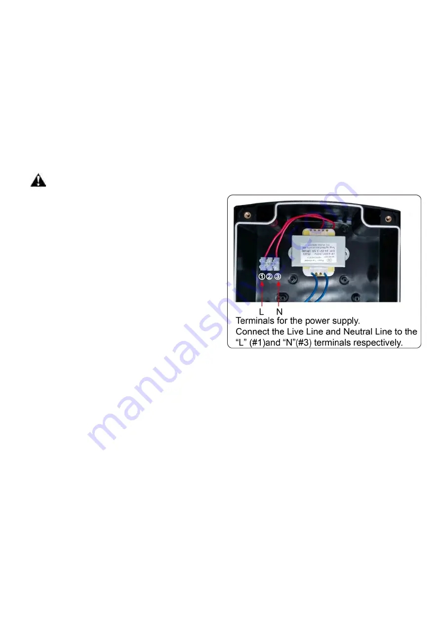
Connect the power supply to the Control Box refers to
the following illustration.
NOTE:
1. Use copper conductors to connect to the power
supply terminals.
2. The wire (not provided) size should be at least
0.75mm
2
(18AWG) which is intended to connect the
power supply.
3. Run the wires in conduit to the control box to
prevent damage to the wires from lawn mowers, weed
eaters and grazing animals.
4. The fuse in the control board is interchangeable. A
10a, 250vac, Φ5*20mm fus
e is suitable to the control
board.
Connecting of the Control Board
Motor connection for PULL-TO-OPEN
Motor 1
Insert the stripped cable wires into the appropriate terminals on the opener terminals block. The red wire should
be inserted into the “
”
terminal, the black wire into “
MOTOR1-“
, the blue wire into
ULT1
, the green
wire into
COM
, and the thin yellow wire into
DLT1
terminal.
Motor 2
Similar as the connection of
Actuator 1
, insert the stripped cable wires into the appropriate terminals on the
opener terminals block. The red wire should be inserted into the “
”
terminal, the black wire into
“
MOTOR2-“
, the blue wire into
ULT2
, the green wire into
COM
, and the yellow wire into
DLT2
terminal.
NOTE:
It is recommended that Gate Opener 1 is installed in the Master Gate, and Gate Opener 2 is installed in
the Slave Gate.
Summary of Contents for KD702
Page 14: ...12...
Page 23: ...21 Quick Setting Guide...
Page 24: ...22...
Page 25: ...23...
Page 26: ...24...


