background image


30

If the option 

Ascending Count

 has been chosen, the parameter 

Start Count 

will be 

enabled. In this edit box one can enter the 

starting state of the JPS file count, (i.e., the numeric 

part of the name of the JPS file created first). This count will be incremented as new JPS files are 
opened. 

New file every

 is associated with a pair of components, an edit box and a drop-down list box. 

Use the list box to select the desired time unit (day, hour or minute). Use the edit box to specify 
the interval (in the selected time unit) in which the current JPS file will be closed and the next one 
will be opened. Note that this interval must be an integer

10

. Also note that some of the multiple files 

created may be shorter (in terms of their duration in time) than it is specified in the corresponding 
edit box.  

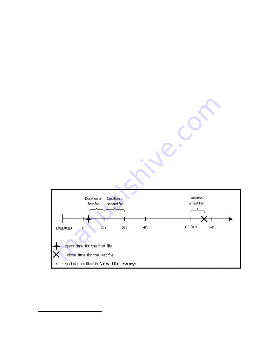
To understand better how multiple files are opened and closed in multiple file mode, let’s consider 
the “artificial” time scale with the origin at 0

h

00

m

00

s


11

) as shown in the figure below. This time 

scale is divided into intervals equal to the period as specified by 

New file every

 fields.  

The first


of the multiple JPS files will be opened immediately after the 

Start

 button 

is pressed. 

The first file will be closed and the second one opened as the 2

nd

 interval starts, for 

example, at 

t=2n

 (see the figure below), etc.  

Time duration of the second and all the following multiple files (maybe except the 
last one) will be exactly equal to the selected file period. 

To stop the multiple file data logging, press the 

Stop

 button. Note that the last file, 

too, can be shorter than is specified in 

New file every


Figure 22. Generation of multiple files 

If the user wants PC-CDU to overwrite the existing files whose names coincide with the names of 
the newly created files, select the 

Overwrite existing files

 checkbox before starting real-

time logging. 


10

 Whatever time unit is selected. 

11

 That is, at the beginning of the day when multiple file logging is started by pressing the 

Start

 button.  

Summary of Contents for PC-CDU

Page 1: ...PC CDU User s Manual Reflects PC CDU Version 2 1 10 MS Build April 1 2002 Last Updated August 6 2002 Copyright Topcon Positioning Systems Inc 2002 All rights reserved ...

Page 2: ...R SUCH DISCLAIMED DAMAGES INCLUDE BUT ARE NOT LIMITED TO LOSS OF TIME LOSS OR DESTRUCTION OF DATA LOSS OF PROFIT SAVINGS OR REVENUE OR LOSS OF THE PRODUCT S USE IN ADDITION TPS IS NOT RESPONSIBLE OR LIABLE FOR DAMAGES OR COSTS IN CURRED IN CONNECTION WITH OBTAINING SUBSTITUTE PRODUCTS OR SOFTWARE CLAIMS BY OTH ERS INCONVENIENCE OR ANY OTHER COSTS IN ANY EVENT TPS SHALL HAVE NO LIABILITY FOR DAMAGE...

Page 3: ...opcon receiver can lead to injury to persons or property and or malfunction of the product The receiver should only be repaired by authorized TPS warranty service centers Users should review and heed the safety warnings in the manual accompanying the receiver MISCELLANEOUS The above Terms and Conditions may be amended modified superseded or canceled at any time by TPS The above Terms and Condition...

Page 4: ...20 4 2 The Main window s menu 21 4 2 1 File Manager window 21 4 2 1 1 Download files 22 4 2 1 2 The Current log file tab 25 4 2 1 3 Download path tab 27 4 2 2 Real Time Logging dialog window 27 4 2 2 1 Single file tab 28 4 2 2 2 Multiple files tab 29 4 2 3 Manual Mode window 33 4 2 4 Receiver Configuration window 34 4 2 4 1 General 35 4 2 4 2 MINTER 39 4 2 4 3 Positioning 42 4 2 4 4 Base 47 4 2 4 ...

Page 5: ...RIPTS 79 Introduction to PC CDU scripts 79 Variables 80 PC CDU commands 80 Receiver commands 82 Running scripts from Windows Explorer 83 APPENDIX B OUTPUT PERIOD SETUP WIZARD 84 APPENDIX C CHANNEL NAVIGATION STATUS CODES 87 ...

Page 6: ...ure 20 Real Time Logging dialog window 28 Figure 21 Multiple files tab 29 Figure 22 Generation of multiple files 30 Figure 23 Overwrite existing files warning 31 Figure 24 Converter to RINEX Setup window 32 Figure 25 Manual Mode window 33 Figure 26 General tab 35 Figure 27 MINTER tab 39 Figure 28 Positioning tab 42 Figure 29 DATUM ID Datum Parameters window 43 Figure 30 GPS tab 45 Figure 31 GLONAS...

Page 7: ... 56 Pop up menu reflecting the information about the selected satellite 75 Figure 57 Position window 75 Figure 58 Plots Configuration window 76 Figure 59 About PC CDU window 77 Figure 60 Wizard s 1st window 84 Figure 61 Wizard s 2nd window 85 Figure 62 Wizard s 3rd window 85 Figure 63 Wizard s 4th window 86 Figure 64 Wizard s 5th window 86 ...

Page 8: ...um INTERface A dedicated user interface designed for TPS receivers NS Navigation Satellite P Precise code PC Personal Computer PLL Carrier Phase Lock Loop PLLC Carrier Phase Lock Loop Control PS Pseudorandom Sequence Receiver Satellite Navigation User Receiver developed and manufactured by TPS RMS Root mean square RNSS Radio Navigational Satellite System RTCM Radio Technical Commission for Maritim...

Page 9: ...st run his her PC CDU in Internet Client Mode Keeps track of the total number and the status of all visible satellites Displays the receiver s current position and time in real time Controls the recording of raw data measurements into the receiver s internal memory Downloads collected raw data measurements log files from the receiver s internal memory onto the computer s disk drives Records in rea...

Page 10: ...s Press CTRL V This format is used to specify keys and key combinations Type the string 194 85 135 59 This format is used to enter various string in formation e g file and directory names as well as user commands To clear the NVRAM 1 Select the option Clear NVRAM from the Tools menu This format is used to describe the sequence of steps that the user must take Note The user is recommended to take n...

Page 11: ...nents in this manual Table 2 Тerms used in this manual to describe standard Windows GUI components GUI component Term Button Edit box or indicator Selected checkbox Unselected checkbox Selected radio button Unselected radio button Progress bar Status bar Spin button File List box Drop down list box Menu Tab Control ...

Page 12: ... Appendix C Channel Navigation status codes shows the list of all available satellite navigation status codes 1 5 System requirements Check that you have the following required or recommended items before installing and using PC CDU PC compatible with Intel Pentium 100 MHz or faster 5 Мbyte free disk space 16 Мbyte RAM or more 32 Мbyte recommended 32 bit operating system such as MS Windows 95 98 M...

Page 13: ...ly PC CDU users encounter problems during installation or use of the program Should you have any problems with PC CDU please contact TPS Customer Support Please be ready to provide TPS Customer Support with the following information Did you try to fix the problem s on your own based on the troubleshooting tips avail able in the manual System hardware specifications of the computer on which you are...

Page 14: ...t the Software Downloads link Finally click on the link Click here to download pccdu_ms zip to start data downloading To download PC CDU Lite select the Utilities link on the Software Center page 2 You will see the dialog box Enter Network Password appears on the screen You are prompted to enter a username and password After you type in this information press OK Figure 1 Figure 1 Dialog box Enter ...

Page 15: ...e the download process press Save Figure 2 Figure 2 Dialog box File Download 4 Use the dialog window Save As to specify the desired destination disk drive folder for the ar chive pccdu_ms zip Figure 3 Figure 3 Select a destination for the archive pccdu_ms zip ...

Page 16: ... files appear in the folder Executable file Pccdu exe Auxiliary binary file lptaccess vxd 2 2 Removing PC CDU The simplest way to remove PC CDU from a system is to delete the whole directory2 that was cre ated when installing PC CDU and in which Pccdu exe and other PC CDU related files reside Also do not forget to delete the PC CDU shortcut if available 1 It is recommended to use C Program Files T...

Page 17: ... full path to Pccdu exe Press OK After you first run PC CDU you will see the file pccdu ini appear in the directory from which the executable has been launched In this INI file PC CDU will store all its settings If you want to have more than one copy of PC CDU each one with its own unique settings you will need to keep these copies in different directories Running dif ferent copies of PC CDU from ...

Page 18: ...at you want to use for the connection 2 From the Baud Rate list box select the desired baud rate The checkbox Infrared port is selected when you want to use an infra red adaptor to establish a connection between your computer and receiver over an in frared data link Connection via an infrared port will be available only if the following conditions are met An appropriate external infrared adaptor i...

Page 19: ...cked It is important to remember that this setting 90º will be ef fective as long as the main window remains open Note however that the original value of Terminal Elevation Mask will not be lost in this case once the main window is closed PC CDU will automatically restore the original mask If Manual mode only is on PC CDU will perform as an input output terminal which allows the user to send comma...

Page 20: ...llected during the communication session between the PC CDU server and PC CDU client New information will be added to the file after another client connects to the PC CDU server If the user wants to view the satellite information and the antenna s current position in the main windows he she must select the Display data on server checkbox Otherwise no informa tion will be displayed in the window If...

Page 21: ...ser can control this receiver exactly in the same manner as if the user s computer were directly connected to the receiver specifically send commands to the remote receiver download log files from the receiver s memory etc In or der to be able to connect to the remote receiver the user first needs to configure his her computer as a PC CDU Client capable of working with the corresponding PC CDU Ser...

Page 22: ...om the client to the server are preceded by the character Messages sent by the server to the client begin with the character The last received message is topmost in the list Figure 8 Chat window 3 2 How to close PC CDU To disconnect from the receiver select the Disconnect option from the File menu Alterna tively you can use the keys CTRL D to close the connection Pressing the Disconnect button wil...

Page 23: ...isconnect has been selected To quit PC CDU select Exit from the File menu Alternatively you can close the program by pressing the keys CTRL X If the receiver has not been disconnected by the time the program is terminated the connection will be automatically broken before PC CDU is closed It is strongly recommended to close the connection with the receiver and close PC CDU prior to switching the r...

Page 24: ...o panels the GPS Satellites panel on the left and GLONASS Satellites on the right which are separated by the Geo XYZ Target box The panels display the basic tracking information parameters for the locked satellites These tracking parameters are described in table 4 The Geo XYZ Target box represents the antenna s current position if available and the time frequency parameters Figure 9 Main window ...

Page 25: ...llite is at maximum elevation it is marked with AZ Azimuth in degrees CA Signal to noise ratio C N0 in the C A channel dB Hz P1 Signal to noise ratio C N0 in the P1 channel dB Hz P2 Signal to noise ratio C N0 in the P2 channel dB Hz TC Time elapsed since the last loss of lock in the C A channel for the corresponding satellite This time is given in minutes or if the symbol is specified in the colum...

Page 26: ...fixed LQ This field reflects the status of the received differential messages and contains the following information Data link quality in percentage Time in seconds elapsed since the last received message Total number of received correct messages Total number of received corrupt messages 6 These geodetic coordinates are computed in WGS 84 regardless of the current value of the par pos datum cur pa...

Page 27: ...S time scale only Receiver date shows the receiver s current date as specified in the corresponding RD message Clock offset describes the time derivative of Tr Trr where Tr designates the re ceiver time Trr designates the receiver reference time For more information about Tr and Trr see the GRIL Reference Manual This parameter is obtained from the DO message and is expressed in parts per million p...

Page 28: ...s navigational information specifically Figure 12 Target tab Lat Lon latitude longitude of the target or of the receiver s antenna ETT NTT Easting to target and Northing to target in the local system with the ori gin at the receiver DTT Distance to target in meters CTT Course to target The rest of the parameters have been described above see the Geo and XYZ tabs To set the target coordinates equal...

Page 29: ...e menu items have shortcut keys For example the user can select the Site item from the Configuration menu with the keys CTRL I Figure 13 The Main window s menu The following sections will describe all available menu items and the corresponding dialog windows in detail 4 2 1 File Manager window To open the File Manager dialog window select the File Manager item from the File menu or press the keys ...

Page 30: ... the data see Figure 14 The green circle indicates the file s that have been successfully downloaded The red circle marks the file that is being downloaded The blue circle indicates the file s in the queue for downloading The user can interrupt the download by pressing the Stop button Files in the destination folder will have the same names and extensions as the original receiver log files Before ...

Page 31: ...trieve this block of data have been made so far Figure 16 Message notifying that a problem occurred while retrieving the current block of data from the receiver If such a problem occurs you may need to try a higher baud rate and or a smaller block size Usually the larger the block size the more efficient the data transfer On the other hand if the connection between the computer and receiver is not...

Page 32: ...irst the download progress indicator can occa sionally display values exceeding 100 Second the last record can be corrupt in the downloaded file If Exclusive mode is on it is impossible to start down loading the current log file without closing it first In other words if the Exclusive mode checkbox has been checked and one wants to start down loading the current log file PC CDU will automatically ...

Page 33: ... on the corresponding filename 2 Specify the desired data recording interval i e data update interval in the Recording interval edit box 3 Set the desired Elevation mask 4 Click the Site parameters button The Site Configuration dialog box will appear Figure 18 Specify the desired Site Name and then select the correct Antenna Status from the corresponding list box Set the Antenna Height parameter a...

Page 34: ...i 5 Press Start A new log file will be created9 and the receiver will start recording data into the file If you set a recording interval that is not supported by the receiver PC CDU will launch a utility called Output Period Setup Wizard For more information on the Wizard see Appendix B Output Period Setup Wizard To stop data recording and close the file press the Stop button To keep track of the ...

Page 35: ...re structurally similar to the Main window For a description of the GUI components that are identical for the Real Time Logging and Main windows refer to 4 1 Below we will focus on the components specific to the Real Time Logging dialog boxes Note the three tabs in the top left corner of the window Single file Multiple files and Select output path For information on the Select output path tab refe...

Page 36: ...the Real Time Logging dialog window The value of Recording interval specified in the Real Time Logging win dow applies only to this mode The Elevation mask edit box is associated with the receiver parameter par out elm cur term 4 2 2 1 Single file tab Figure 20 Real Time Logging dialog window In this mode Figure 20 PC CDU will record receiver data into one specific file on the host com puter In th...

Page 37: ...e name of the setting implies Prefix determines the prefix part of the filename By default PC CDU will use the site name specified in the Site Configuration dialog window as the file name prefix The Numbering edit box allows you to select the desired file numbering scheme If the option Date Time is selected the numeric part of the filename will look as fol lows YDDDHHMM where Y last digit of the y...

Page 38: ...nsider the artificial time scale with the origin at 0h 00m 00s 11 as shown in the figure below This time scale is divided into intervals equal to the period as specified by New file every fields The first of the multiple JPS files will be opened immediately after the Start button is pressed The first file will be closed and the second one opened as the 2nd interval starts for example at t 2n see t...

Page 39: ... the Start button to start data log ging In this case the numeric parts of the names of the JPS files recorded will be incremented starting from the first unused value not necessarily from 0000 If the Autoconvert to RINEX checkbox is selected PC CDU will automatically convert all newly created JPS files to RINEX Note that this conversion is performed on the move If you want to use the Autoconvert ...

Page 40: ... marker In the Application edit box the full path to jps2rin exe must be entered Use the button Browse to select the desired filename path instead of typing it Use the checkbox Exclude GPS Exclude GLONASS to exclude from the resulting RINEX files all raw data measurements ephemeris data corresponding to GPS GLONASS Use the checkbox Exclude L1 Exclude L2 to exclude from the resulting RINEX files al...

Page 41: ...om the File menu or press the keys CTRL M This window Figure 25 allows direct control of the receiver by using GRIL commands In manual mode PC CDU serves as a terminal communicating with the receiver i e it allows one to send various receiver commands and get responses to these commands For a complete list of com mands supported by TPS receivers refer to the GRIL Reference manual This document is ...

Page 42: ...riginal baud rate on Disconnect option has been selected In other words if one wants to restore the receiver port s original baud rate it can be achieved ei ther by selecting the Connect item from the File menu or through the Manual Mode win dow In the second case make sure that the command used to change the receiver port s baud rate is executed immediately before clicking the Disconnect button T...

Page 43: ... the desired script file to the receiver thus enabling several necessary receiver settings with a single operation The button Set all parameters to defaults does exactly what its name implies 4 2 4 1 General Figure 26 shows the Receiver Configuration window s General tab Figure 26 General tab In the Terminal Elevation Mask edit box the user enters the minimum elevation i e the elevation mask angle...

Page 44: ...ill have to power the receiver off and then back on The Regency and Odyssey receivers using JPS_4_2 are capable of automatically detecting an external antenna without switching the receiver off and back on Antenna Status The indicator Current Input shows what antenna type is actually being used by the receiver int the internal antenna is being used ext an external antenna is being used This flag r...

Page 45: ...tery B Auto receiver will automatically detect and charge the detected batteries This setting is associated with the receiver parameter par pwr charge bat Use the Speed list box to set the desired speed of battery charge cycle You can se lect between Normal and Fast dc levels The corresponding receiver parameter is par pwr charge speed The flag Current Mode shows which of the batteries a b or none...

Page 46: ...ports With the Slots list box the user governs power output on the internal slots On means that all slots are powered if the receiver is turned on Off means that internal slots will not be powered even if the receiver is turned on Always means that internal slots will be powered even if the receiver is turned off The list box is associated with the receiver parameter par pwr slots Turn on off Slot...

Page 47: ...ity called Output Period Setup Wizard For more in formation on the Wizard see Appendix B Output Period Setup Wizard Elevation mask for Log file specifies the minimum elevation angle for the satellites whose data will be put in the receiver files logged via Minter i e by pressing FN The corresponding re ceiver parameter is par out elm cur log File name prefix specifies what prefix will be added to ...

Page 48: ...kbox Automatically remove old files is selected the receiver will start should there be no free space left in the receiver memory overwriting the least recent files14 The corresponding receiver parameter is par log rot rmold FN key mode These two radio buttons are used to program how the receiver will react to clicking FN i e keeping the button depressed for less than one 1 second In LED blink mod...

Page 49: ...d the receiver will start recording data in this file Before a power failure oc curred the string Always append to the file had a non empty value but data logging hadn t been started yet A file with this name will not be opened and data logging will not be started after the power is restored A file with this name will not be opened and data logging will not be started after the power is restored A...

Page 50: ...for user convenience They mirror the same named checkboxes from the Rover tab If the Standalone checkbox has been checked and the rover receiver is being run in differential mode the receiver will report its current standalone position instead of the DGPS or RTK posi tion if the latter is unavailable in the current epoch The corresponding receiver pa rameter is par pos mode sp Note that the checkb...

Page 51: ...on This setting is associated with the receiver parameter par pos datum cur Pressing the Datum Parameters button will open the Datum ID Datum Parameters window Figure 29 In this window one cannot only view the ellipsoid and trans formation parameters of the datums selectable from the Current Datum list box but also edit the transformation parameters for USER and P90 In addition the ellipsoid param...

Page 52: ...onding receiver parameter is par pos sp tropo Note that the above mentioned receiver parameters par pos sp meas par pos sp iono and par pos sp tropo apply only to absolute position computa tion Satellite management Satellites tracked The checkboxes GPS and GLONASS are used to allow tracking of GPS and GLON ASS satellites respectively The GPS checkbox is associated with the receiver parame ter par ...

Page 53: ... corresponding satellites are enabled for position computa tion In Figure 30 GPS satellite PRN 4 is disabled for position computation A GPS satellite s system number is identical to its PRN number Use the buttons All to lock and All to use to select all GPS satellites at one time Use the buttons None to Lock and None to use to deselect all GPS satellites at one time The second tab as its name impl...

Page 54: ...AAS tab A WAAS enabled TPS receiver allows simultaneous tracking of two WAAS satellites Either of the WAAS satellites is allocated its own channel Below it will be shown how to set up Channel 1 Channel 2 is handled in the same manner The checkbox Channel 1 if selected allows you to specify necessary settings for the desired WAAS satellite One uses the spin boxes Set WAAS and as GPS to associate th...

Page 55: ...Corrections are available will be used in position computation Note that this is the default option for the radio button group To make WAAS Channel 2 settings use the same receiver parameters but re placing 1 with 2 e g par waas 2 sat for par waas 1 sat If the checkbox Enable output of true WAAS PRN numbers is selected the WAAS satellites will have their true WAAS PRNs not GPS associated in the co...

Page 56: ...r GLON ASS Pressing the Datum Parameters button will open the Datum ID Datum Parameters window In this window you can not only view the ellipsoid and transformation parameters of the datums selectable from the Current Datum list box but also edit the trans formation parameters for USER and P90 In addition one can edit the ellipsoid parameters of USER in this window Structurally this window is simi...

Page 57: ...ite constellations included in the RTCM message types 18 19 20 and 21 These checkboxes are associated with the receiver parameter par rtcm base sys If the Pseudo range smoothing checkbox is selected the receiver will use smoothed pseu doranges in the RTCM message types 19 through 21 This checkbox corresponds to the receiver pa rameter par rtcm base smooth CMR Settings The Station ID edit box corre...

Page 58: ...d message types between 3 and 7 The spin box is associated with the receiver parameter par cmr base glo type Click the Configuration of Receiver Ports button to go to the Ports tab For a descrip tion of this tab refer to section 4 2 4 6 of this manual 4 2 4 5 Rover In the tab one can configure a receiver as a rover station see Figure 34 Figure 34 Rover tab The Positioning Mode radio button group p...

Page 59: ...se of the obtained position estimates Best means that the solution has the least RMS error The Best checkbox is associated with the receiver parameter par pos cd mult best In the CD Corrections max age edit box the user can set the maximum age in seconds of the code differential corrections used for position computation Here one can enter an integer value between 1 and 1200 The default is 30 If th...

Page 60: ...rresponding parame ter is par pos pd dyn The Ambiguity Fixing Level radio buttons govern the process of the RTK engine fixing inte ger ambiguities The RTK engine uses the ambiguity fix indicator when making a decision whether to fix ambiguities or not Low Medium and High correspond to the indicator s 95 99 5 and 99 9 states respectively The higher the specified confidence level the longer the inte...

Page 61: ...s The list box Source serves to specify the source port from which the receiver will use differen tial data for position computation in RTK mode This list box is associated with the receiver parame ter par pos pd port CMR Settings With the GLONASS message spin box the user assigns the message type for GLONASS meas urements Make sure that both the reference station and rover receiver use the same m...

Page 62: ...ns that the port will neglect any incoming data Command the port is in command mode In this mode the port recognizes the com mands sent by the user Echo the port is in echo mode Being used in this mode the receiver port redirects all incoming data to an output stream Note that output stream may be either a port or the current log file RTCM the port is in RTCM input mode CMR the port is in CMR inpu...

Page 63: ...erval the Period edit box PC CDU will run a utility called Output Period Setup Wizard For more informa tion on the Wizard see Appendix B Output Period Setup Wizard To set the baud rate for the corresponding receiver port use the Baud rate list box The list box is associated with the receiver parameter par port rate The checkbox RTS CTS enables disables hardware handshaking for the port The checkbo...

Page 64: ... list box intends to specify the method used to transmit data Off internal modem is turned off FHSS internal modem uses frequency hopping spread spectrum technique DSS internal modem uses direct sequence spread spectrum technique These list boxes are associated with the receiver parameter par dev modem a type With the Antenna radio buttons the user sets the antenna type the modem uses Int stands f...

Page 65: ...with respect to the selected reference time grid using the Offset ms edit box for millisecond part and Offset ns for nanosecond part These four edit boxes are associated with the receiver parameters par dev pps a offs ms par dev pps b offs ms par dev pps a offs ns and par dev pps b offs ns respectively With the Period of marked pulses edit box the user specifies the period of the marked 1PPS signa...

Page 66: ...ev event a lock and par dev event b lock respectively The Status indicator shows whether the receiver clock is actually being synchronized with the event signals or not If you see on in the field it means the synchronization has been done success fully These fields relate to the receiver parameters par dev event a locked and par dev event b locked respectively In some cases however it can be neces...

Page 67: ...e Anti Interference radio button group Figure 39 the user enables mode allowing the TPS receivers to suppress the impact of narrow band interferences The user can assess the presence of interference based on the following information When the number of tracked satellites is fewer by 2 or greater than the number of satellites in view When the signal to noise ratio C N0 in the C A channel for the sa...

Page 68: ...s associated with the receiver parameter par raw corr ca code If one uses a pair of receivers in RTK mode select the checkbox Carrier multipath reduction for both receivers The checkbox is associated with the receiver pa rameter par raw corr ca carrier Loops Management In this subtab the user can configure the settings that deal with the receiver capability of searching acquiring and tracking the ...

Page 69: ...daptive Guided Loops checkbox one enables disables the use of adap tive guided loops If the user selects the checkbox the receiver will adjust the guided loops band widths depending on the actual strengths of the signals tracked The weaker the signals the nar rower the bandwidths The checkbox corresponds to the receiver parameter par raw gdl adapt With the Enable P L1 and P L2 tracking checkbox th...

Page 70: ...2 common loop checkbox to avoid the loss of L2 phase tracking in dy namic applications due to antenna rotation around its axis The checkbox corresponds to the re ceiver parameter par raw clp2 loop External Frequency The settings on this subtab Figure 42 allow the operator to configure the use of reference fre quency it may be either high stability external frequency or the receiver s internal crys...

Page 71: ...ecified in the Ext frequency value edit box locked indicates that the receiver is using the external frequency The field is associated with the receiver parameter par frq stat With the Ext freq signal amplitude field the user can estimate the external frequency signal amplitude off indicates that the internal oscillator is actually being used low indicates that the external frequency signal s ampl...

Page 72: ...ked guarantees that the receiver s 20 MHz output will have long term stability not necessarily short term stability However there is a way to as sure that both of these characteristics will be good enough It can be done by se lecting Enable Co op tracking on the Loops Management subtab The radio buttons are associated with the receiver parameter par osc mode Raw Data Management This subtab which i...

Page 73: ...the method used for smoothing Doppler There are three available methods 0 Receiver outputs raw unsmoothed Doppler Instantaneous yet rather noisy Dop pler measurements 1 Doppler is computed using two consecutive carrier phase measurements Car Phase i and CarPhase i 1 where i stands for the current epoch Such Doppler meas urements are less noisy than in the first case 2 Doppler is computed using onl...

Page 74: ...2 5 Site Configuration window To open the Site Configuration dialog window select the Site item from the Configuration menu or press the keys CTRL I This window serves the same purposes as the Site Configuration window described in 4 2 1 2 4 2 6 Target Position window To go to the Target Position window either select the Target Position from the Configuration menu or press the keys CTRL T Target c...

Page 75: ... is port C for the Legacy Legacy E Legacy H Regency HiPer Odys sey E and port B for the Odyssey To set the baud rate of the modem communicating with the receiver use the Connect to modem at bitrate list box It is normally 38400 bps If one wants the receiver automatically to detect the baud rate select Auto Next select the method of modem connection For most RFM96 models you can use Search for mode...

Page 76: ...s and protocol details Figure 49 Figure 49 Configuration tab PDL configuration settings In the RF Channel list box the user can choose the desired channel Once the change has been made press the Apply button to program the radio Be very careful to let the program complete its programming cycle and then press Disconnect Any interruption in power can cause the radio to lose its memory map If this ha...

Page 77: ...alize file system To initialize the file system in the connected receiver select the Initialize file system item from the Tools menu This procedure is to some extent similar to disk formatting It results in erasing all of the files inside the receiver After pressing Initialize file system you will be prompted to confirm the com mand Figure 51 In practice you do not execute this procedure very ofte...

Page 78: ...learing the NVRAM these parameters are set correctly PC CDU will prompt you to check these settings by opening the Receiver Configuration dialog window In addition the NVRAM is used to keep information about the receiver file system Note that after clearing the NVRAM the receiver s FN LED will flash yellow for a few seconds indicating that the receiver is scanning checking the file system 4 2 10 R...

Page 79: ...he receiver options are available for your receiver Second this window allows the user to update the receiver options by loading a new receiver option file with the extension jpo After pressing the Load button PC CDU will prompt the user to enter the name of the corresponding jpo file When the loading of the new re ceiver option file is over in the status bar one will see the comment Option loaded...

Page 80: ...ot displays the current receiver position relative to the position specified in the Target position window The most current receiver position is shown by a red point Status bar contains the following information average latitude longitude and ellipsoidal height of the receiver s position over the en tire set of obtained position estimates horizontal position RMS error vertical position RMS error t...

Page 81: ...When you press the button Fit all points PC CDU will automatically change the scale of the Scatter plot allowing you to view all positions starting from the time PC CDU established the connection to the receiver After you press Target to average PC CDU sets the target position equal to the average re ceiver s position If this window is closed the positions displayed in the Scatter plot and informa...

Page 82: ...le through the Elevation MaskForm win dow which appears immediately after pressing the Elevation mask button Also the user can see four DOP characteristics specifically GDOP Geometric 3 position coordinates plus clock offset in the solution PDOP Position 3 coordinates HDOP Horizontal 2 horizontal coordinates VDOP Vertical height only A dynamically changing histogram shows the signal to noise ratio...

Page 83: ... the Satellites window click the Clear data button 4 2 14 Position window To go to the Position window select the Position item from the Plots menu The graphs in the Position window see Figure 57 show the difference in meters between latitude longitude of the current receiver position and latitude longitude entered in the Target position window over the interval in seconds specified by the user in...

Page 84: ...n click Define Custom Colors To the right of Basic colors you will see a custom palette where you can mix your own color After selecting the color you want click Add to Custom Colors and then click OK In the Scatter group box the user can change the settings related to the Scatter window With the Plot Width edit box the user specifies the length of the axes on the plot The Tick Interval edit box s...

Page 85: ...ions of the receiver s antenna The default value is 3600 When the buffer is full the new values over write the oldest This circular buffer is used with the aim of saving the computer memory consump tion when the graphs have been being monitored for a long time continuously during several hours days etc To commit any changes that you have made without closing the window click Apply 4 2 16 About PC ...

Page 86: ...to write the current receiver parameters and options into an ASCII file This file helps technicians discover the source of the problem and then remedy it Before contacting TPS Customer Support about any problems with PC CDU re ceiver etc please do the following 1 Run PC CDU 2 Establish the connection between PC CDU and the receiver 3 Click Help and then click About or alternatively press CTRL U 4 ...

Page 87: ...s the button Close editor It is recommended to save scripts using the extension jpc To run a script through the command line of the Manual Mode window First enter the script name with the character which is followed by the script name Next specify necessary script arguments if required Finally press the Send command button Script arguments should be delimited by either spaces or commas If some of ...

Page 88: ...e of script execution it will either contain the last of the receiver s positive acknowledgements i e the most recent of the RExxx replies or remain empty After getting RExxx from the receiver PC CDU will search the received sequence for the last of the symbols it contains PC CDU does not assign to the variable 0 the entire RExxx reply but only the characters following immediately after the last s...

Page 89: ...U will not show echo off and echo on com mands Default is on exit Stops script execution disconnects PC CDU from the receiver and exists PC CDU goto label name Jumps to the line following immediately after label name If PC CDU can t find such a label in the script this command is just ignored and PC_CDU continues with the script Sends the argument to the receiver as is without making any substitut...

Page 90: ...ese will be substituted by PC CDU for some specific val ues before sending the corresponding command to the receiver If the user sends a receiver com mand that starts with command label PC CDU will wait for the receiver to reply and if a reply is received it will save the reply to the variable 0 Currently the character is used in GRIL commands only to delimit the command checksum It should not cau...

Page 91: ...eceiver is Odyssey goto end IsLegacy echo Receiver is Legacy goto end IsEurocard echo Receiver is Eurocard end stop Running scripts from Windows Explorer Files with the extension jpc are automatically associated with PC CDU It means that you can launch PC CDU specifically in Manual mode by clicking on a script in the file directory tree It can be achieved with the use of Windows Explorer My Comput...

Page 92: ...position PC CDU will open this Wizard only if you try to specify an incorrect recording interval Once the Wizard is run follow the onscreen instructions to adjust the typed values The following five figures which are given here just for the user s convenience show how the Out put Period Setup Wizard windows look These windows are listed in order of appearance Figure 60 Wizard s 1st window ...

Page 93: ...85 Figure 61 Wizard s 2nd window Figure 62 Wizard s 3rd window ...

Page 94: ...86 Figure 63 Wizard s 4th window Figure 64 Wizard s 5th window ...

Page 95: ...Alert flag from the word HOW is set 1 12 URA indicates the absence of accuracy prediction for this SV 1 13 This SV is excluded from position computation by the user 14 SV with this frequency channel number is excluded from position computation by the user 2 15 This SV is excluded from solution since its system number is unknown 2 16 This SV has elevation lower than the specified mask angle 17 Rese...

Page 96: ...processing 54 P L2 slot is used in RTK processing 55 P L1 P L2 measurements are used in RTK processing 56 62 C A P L2 measurements are used in RTK processing 63 Reserved 1 GPS only 2 GLONASS only Codes 0 3 and 45 62 will show for the given satellite which raw data measure ments have been used in position computation The rest codes will indicate why this satellite has been excluded from position co...

Reviews: