background image

45

CHART FUNCTIONS UNIQUE TO THE MC-4S

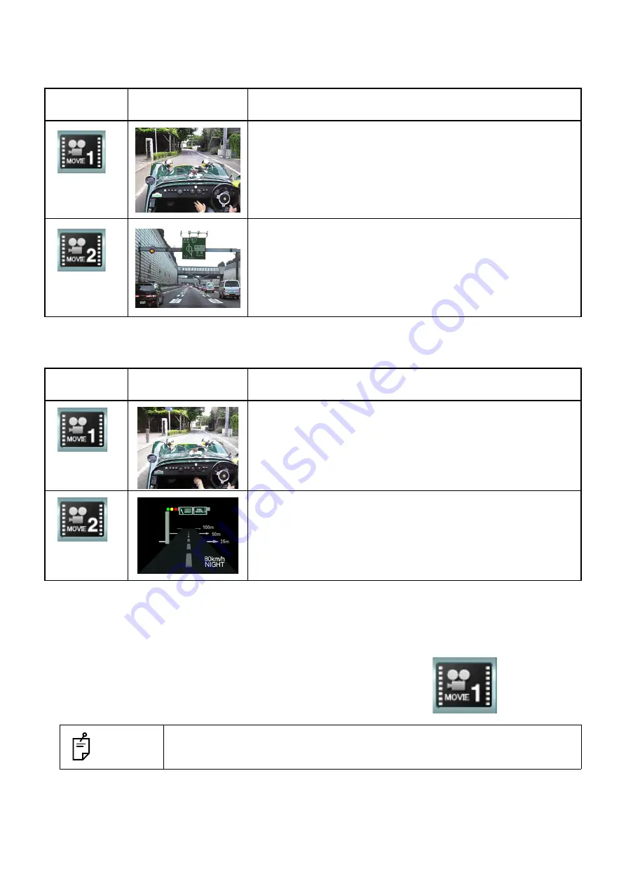
Movie file

• D type

• F type, H1 type

Playback of movie

1

Select "MOVIE" from the chart page.
The movie is played.

Chart page 
icon

MC-4S

Remarks

This movie is the 3D movie.
Watch this movie through the polarized lens set on the measur-
ing head of the CV-5000.  It will be seen as a stereoscopic
vision.

This movie shows the landscape photographed from the car
running on a superhighway.

Chart page 
icon

MC-4S

Remarks

This movie is the 3D movie.
Watch this movie through the polarized lens set on the measur-
ing head of the CV-5000.  It will be seen as a stereoscopic
vision.

This movie is the animation showing the scene "Traveling on
the road at night".

 NOTES

Select any other chart.  The playback of the movie is finished and the selected
chart is indicated.

Chart page icon (example)

Summary of Contents for MC-4S

Page 1: ...USER MANUAL MIRROR CHART MC 4S ...

Page 2: ......

Page 3: ...TION and familiarize yourself with the correct safety procedures prior to operating the MC 4S Keep the user manual on hand for future reference This instrument should be used in conjunction with a CV system There are three methods to operate the MC 4S through the CV 5000 Operate the MC 4S with the 1Dial Controller KB 50S Connect the mouse to the monitor and operate the MC 4S with the mouse Connect...

Page 4: ...ject to change without prior notice and without legal obligation 3 The contents of this manual are correct to the best of our knowledge Please inform us of any ambiguous or erroneous descriptions missing information etc 4 Original Instructions This instruction manual was originally written in English 2011 TOPCON CORPORATION ALL RIGHTS RESERVED ...

Page 5: ... 16 REGISTERING THE VISUAL ACUITY CHART 16 SETTING THE INSTALLING DISTANCE 18 SETTING THE ALIGNMENT EMITTER 19 HOW TO ADJUST ALIGNMENT 20 INDICATION OF CHART 21 TEST CHART LIST 21 OPERATION AFTER USE 26 CHART FUNCTIONS UNIQUE TO THE MC 4S 27 BLACK AND WHITE REVERSING FUNCTION 27 CHARACTER CONTRAST CHANGING FUNCTION 29 ACTIVE CHART 34 DISPLAY OF STILL IMAGE MOVIE 39 REGISTRATION USER CUSTOMIZE AND ...

Page 6: ...EFFECT 63 ENVIRONMENTAL CONDITIONS FOR USE 63 STORING METHOD USAGE PERIOD AND OTHERS 63 ELECTRIC RATING 64 DIMENSIONS AND WEIGHT 64 SYSTEM CLASSIFICATION 64 OPERATION PRINCIPLE 65 CHECKPOINTS FOR MAINTENANCE 65 DISPOSAL 65 PATIENT S ENVIRONMENT 66 REQUIREMENTS FOR THE EXTERNAL DEVICE 66 ELECTROMAGNETIC COMPATIBILITY 67 REFERENCE MATERIAL 71 SHAPE OF PLUG 71 ...

Page 7: ...other liquids To avoid fire and electric shock do not insert metal objects into any clearance etc To avoid fire in the event of an instrument malfunction immediately turn off the power switch and remove the power plug from the outlet if you see smoke coming from the instrument or if you detect other problems Don t install the instrument where it is difficult to disconnect the power plug from the o...

Page 8: ... with IEC60601 1 2 Ed 3 0 2007 This instrument radiates radio frequency energy within standard and may affect other devices in the vicinity If you have discovered that turning on off the instrument affects other devices we recommend you change its position keep a proper distance from other devices or plug it into a different outlet Please consult the dealer from whom you purchased the instrument i...

Page 9: ...pport metal fixture are loose For details refer to USER MAINTENANCE ITEMS on page 58 of this manual DISCLAIMERS TOPCON shall not take any responsibility for damage due to fire earthquakes actions by third per sons and other accidents or damage due to negligence and misuse by the user and any use under unusual conditions TOPCON shall not take any responsibility for damage derived from inability to ...

Page 10: ... to these will prevent the problems noted Symbol IEC ISO Publication Description IEC 60417 5032 Alternating Current IEC 60417 5031 Direct current IEC 60417 5957 For indoor use only IEC 417 5265 Off only for a part of EQUIPMENT IEC 417 5264 On only for a part of EQUIPMENT ISO 7010 W001 General warning sign ISO 7010 M002 Refer to the instruction man ual ISO 7000 2497 Date of manufacture ISO 7000 249...

Page 11: ...id injury caused by electric shock do not open the cover Ask your dealer for service 2 WARNING Do not the touch the terminal while using the AC adapter Doing this may cause injury 3 CAUTION Only install the maintenance cap when cleaning the instrument If you do not follow this the chart may not be displayed correctly and cause an incorrect test result 4 CAUTION Install the support metal fixture If...

Page 12: ...ntity If one of the standard components is not included in the package contact your dealer or your local TOPCON office listed on the back cover BPM030S12F04 for USA and Canada JMW160KA1200F09 for outside the USA and Canada User manual Instruction manual 1 Power cord 1 AC adapter 1 Dust cover 1 Alignment emitter 1 Dry battery 2 Image cable 1 USER MANUAL MIR ROR CHART MC 4S ...

Page 13: ...en the instrument is plugged into the outlet When the power switch is turned ON this lamp is lit in green and the instrument can receive the image signal Maintenance cap Use this in maintenance Sensor detector unit This unit receives the signal from the alignment emitter to adjust the eye position CAUTIONS To avoid electric shock do not touch the external connection terminal and the patient at the...

Page 14: ...sed to connect the AC adapter Support metal fixture This reinforces the instrument s stability Screw for support metal fixture These affix the support metal fixture onto the instrument Adjuster Used to adjust the inclination when installing the instrument NOMENCLATURE OF ALIGNMENT EMITTER NOTES Cover is attached to the analog VGA connector Don t use this connector 8 5 9 6 10 7 5 6 7 8 9 10 Magnet ...

Page 15: ...t be loosened If the screw becomes loosened the instrument may fall and cause damage and or injury To remove the support metal fixture ask your service personnel If the instrument is not installed along a wall it may fall and cause injury NOTES On the chart window there is sometimes noticeably unevenness on the back ground due to interfering light To prevent sunlight or interfering light from com ...

Page 16: ... CV 5000 user manual for the connection method for the CV system NOTES This instrument can only be connected to the following devices CV POWER SUPPLY UNIT WITH BUILT IN PERSONAL COMPUTER or the personal com puter connected to the CV POWER SUPPLY UNIT WITH EXTERNAL PER SONAL COMPUTER This instrument cannot be connected to the CV power supply unit and the personal computer connected with the CV powe...

Page 17: ...AC adapter 3 Insert the power cord plug into the 3 plug AC outlet with proper grounding WARNINGS To avoid fire and electric shock in case of leakage be sure to use a grounded outlet Do not connect to outlets that are not grounded To avoid electric shock use only the attached AC adapter CAUTIONS To avoid electric shock do not handle the plugs with wet fingers ...

Page 18: ...rt that is necessary to use this instrument 1 Turn on this instrument and the power supply unit When operating through a personal computer When using this instrument by connecting to a personal computer it is necessary to display the desktop on the screen before starting the CV software Set Resolution 640 x 480 32 bit color Screen refresh rate 70Hz or more for the MC 4S monitor and connect it as t...

Page 19: ...Type Then select MC 4S for Chart monitor selection 5 Touch the Chart software config button and then the Chart settings button The CHART SETTINGS screen appears Set Examination distance according to the real test distance Touch the OK button and then the Exit button The Chart settings screen appears again 6 Touch the OK button and then the Exit button to save the setting and finish the procedure ...

Page 20: ...0cm as the default when shipped CAUTIONS To avoid electric shock when setting the installing distance do not make any contact with the patient and the sensor detector unit at the same time Before setting the installing distance make sure that the power switch of the instrument is OFF If it is ON you may receive an electric shock NOTES To change the installing distance setting ask your service pers...

Page 21: ...e cover at the rear of the sensor detector unit Channel table Setting of alignment emitter and instrument CAUTIONS To avoid electric shock when changing the setting of the alignment emitter do not make any contact with the patient and alignment emitter at the same time NOTES To change the setting of the alignment emitter ask your service personnel NOTES To change the setting of the instrument ask ...

Page 22: ...n the patient watches the chart through the TOPCON CV 5000 or other instruments press the alignment emitter switch beside the examination win dow If the alignment emitter is placed too far away in the back and forth direction sometimes the height is not adjusted correctly though it is beside the eye or examination window When using the alignment emitter let it face the sensor detector unit of the ...

Page 23: ...right side of the chart When a large chart is selected the visual acuity is indicated at the upper or lower right Sometimes even if the system is set to indicate the visual acuity in large size it is forcedly indicated in small size Hiragana chart Visual acuity 0 05 Hiragana chart Visual acuity 0 1 and 0 15 Hiragana chart Visual acuity 0 2 0 3 and 0 4 Hiragana chart Visual acuity 0 5 0 6 and 0 7 H...

Page 24: ...e chart Binocular balance polarization chart Reticle heterophoria chart white back ground Reticle heterophoria chart black back ground Cross chart with fixation target white back ground Cross chart with fixation target black back ground Cross ring chart Fixation target chart Cyclophoria chart white background Cyclophoria chart black background One vertical line char acter chart One horizontal line...

Page 25: ...er E chart Visual acuity 0 5 0 6 and 0 7 Letter E chart Visual acuity 0 8 0 9 and 1 0 Letter E chart Visual acuity 1 2 1 5 and 2 0 Landolt ring chart Visual acuity 0 05 Landolt ring chart Visual acuity 0 1 and 0 16 Landolt ring chart Visual acuity 0 2 0 3 and 0 4 Landolt ring chart Visual acuity 0 5 0 6 and 0 7 Landolt ring chart Visual acuity 0 8 0 9 and 1 0 Landolt ring chart Visual acuity 1 2 1...

Page 26: ...ation chart Reticle heterophoria chart white back ground Reticle heterophoria chart black back ground Cross ring chart Fixation target chart Cross chart with fixation target white back ground Cross chart with fixation target black back ground Aniseikonia chart verti cal Aniseikonia chart hori zontal Stereoscopic vision chart Worth 4 Dots chart Cross cylinder chart 1 Cross cylinder chart 2 Cross cy...

Page 27: ...0 and 15 Letter E chart Visual acuity 600 Letter E chart Visual acuity 400 Letter E chart Visual acuity 200 Letter E chart Visual acuity 150 Letter E chart Visual acuity 100 and 80 Letter E chart Visual acuity 70 60 and 50 Letter E chart Visual acuity 40 30 and 25 Letter E chart Visual acuity 30 25 and 20 Letter E chart Visual acuity 20 15 and 10 Numeral chart Visual acuity 200 and 150 Numeral cha...

Page 28: ...children Visual acuity 40 30 and 20 ETDRS chart 1 ETDRS chart 2 RG chart Binocular balance polarization chart Cross chart with fixation target white back ground Fixation target chart Aniseikonia chart Stereoscopic vision chart Worth 4 Dots chart Cross cylinder chart 1 Cross cylinder chart 2 Cross cylinder chart 3 Astigmatism chart 1 Astigmatism chart 2 Astigmatism chart 3 Cross chart with fixation...

Page 29: ...charts except the screening chart An example of the test chart icon displayed on the chart page of the KB 50S Reversing the black and white display condition 1 Select the visual acuity chart which can be reversed from the chart page 2 Press the Shift key on the KB 50S and touch the Reverse button among the function buttons at the bottom of the screen 3 On the MC 4S the chart is displayed in the re...

Page 30: ...mouse personal com puter click the button displayed on the test screen of Step 2 The black and white reverse mode is kept while the following operations are being executed Changing to any other visual acuity chart applicable to this reverse mode Setting and moving the vertical mask horizontal mask and character mask Executing the random mode NOTES To cancel the reversed black and white condition t...

Page 31: ... contrast mode In Single rate character contrast mode the character contrast on the chart can be changed in seven steps 2 5 5 10 12 5 25 50 and 100 Relevant chart This function is applied to all the visual acuity charts except the screening chart An example of the test chart icon displayed on the chart page of the KB 50S Setting Single rate character contrast 1 Select the visual acuity chart appli...

Page 32: ...ting the visual acuity refer to the COMPU VISION CV 5000 USER MANUAL 2 The visual acuity value with the contrast value which is being displayed is recorded NOTES When operating the CV system through a mouse personal computer you can change the contrast with the same procedure When changing the chart to another that is applicable to this mode the Sin gle rate character contrast mode is kept While t...

Page 33: ...ral rate character contrast mode the contrast conditions of the five stages 25 12 5 10 5 and 2 5 can be displayed on one chart at a time Relevant chart This function is applied to a visual acuity chart having 3 lines and 5 columns An example of the test chart icon displayed on the chart page of the KB 50S NOTES When operating the CV system through a mouse personal computer you can cancel the contr...

Page 34: ...ntrast setting menu As shown below on the MC 4S the chart is displayed under the condition that the columns are different in contrast by stages 25 12 5 10 5 and 2 5 from the leftmost NOTES When operating the CV system through a mouse personal computer you can change the contrast with the same procedure When changing the chart to another that is applicable to this mode the Plural rate character con...

Page 35: ... contrast value is recorded Canceling Plural rate character contrast 1 Touch the Contrast button among the function buttons at the bottom of the screen on the KB 50S to display the contrast setting menu 2 Touch the Exit button on the contrast selection menu and the plural rate character contrast mode is canceled NOTES When operating the CV system through a mouse personal computer you can cancel th...

Page 36: ...charts are applicable to this function Executing Prism simulation 1 Select the chart applicable to Prism simulation from the chart page 2 Perform the phoria measurement according to normal procedure 3 Touch the Simulate button among the function buttons at the bottom of the screen on the KB 50S 4 The prism lens which is set on the measuring head of the CV 5000 is temporarily canceled As shown belo...

Page 37: ...moves right Turn the dial counterclockwise and the vertical line moves right and the horizontal line moves left Vertical phoria measurement Turn the dial clockwise and the vertical line moves down and the horizontal line moves up Turn the dial counterclockwise and the vertical line moves up and the horizontal line moves down NOTES When operating through a mouse personal computer do not turn the di...

Page 38: ...re size at the left side is changed as shown below Adjust the size so that the patient can see the right and left targets in the same size 4 Operate the dial according to Dial Navigation The changeable size range is 10 to 10 with the size rate of the left square against the right one The size during changing is displayed on the function button at the bottom of the screen on the KB 50S Turn the dia...

Page 39: ...matism chart where only one radial line color is deeper than others the deeper line can be changed with the dial To measure the cylinder axis by using the astigmatism chart let the patient align the deeper line on the chart with the line whose color is deeper in his her vision Relevant chart The following charts are applicable to this function NOTES When operating through a mouse personal computer...

Page 40: ...ged in the dial turning direction Let the patient align the deeper color line on the chart with the line whose color is deeper in his her vision 4 To exit the Astigmatism chart rotation mode touch the Rotate button again The chart of the MC 4S is returned to the status before executing the Astigmatism chart rotation function The cylinder power before executing the Astigmatism chart rotation mode i...

Page 41: ...prepared by the customer Preinstalled contents When shipped 20 files of still images 2 files of movies and 9 files of still images for slideshows for each of D type F type and H1 type are provided in the MC 4S Still image file D type Chart page icon MC 4S Test screen Remarks Still image is displayed on MC 4S and the test screen Still image is displayed on MC 4S and the test screen Still image is d...

Page 42: ...nd the test screen Still image is displayed on MC 4S and the test screen Still image is displayed on MC 4S and the test screen Still image is displayed on MC 4S and the test screen Still image is displayed on MC 4S and the test screen Still image is displayed on MC 4S and the test screen Chart page icon MC 4S Test screen Remarks ...

Page 43: ...g head of the CV 5000 It will be seen as a stereo scopic vision This still image is the 3D still image Watch this image through the polarized lens set on the measuring head of the CV 5000 It will be seen as a stereo scopic vision This still image is the 3D still image Watch this image through the polarized lens set on the measuring head of the CV 5000 It will be seen as a stereo scopic vision This...

Page 44: ...vision Chart page icon MC 4S Test screen Remarks Still image is displayed on MC 4S and the test screen Still image is displayed on MC 4S and the test screen Still image is displayed on MC 4S and the test screen Still image is displayed on MC 4S and the test screen Still image is displayed on MC 4S and the test screen Still image is displayed on MC 4S and the test screen Chart page icon MC 4S Test ...

Page 45: ... the polarized lens set on the measuring head of the CV 5000 It will be seen as a stereo scopic vision This still image is the 3D still image Watch this image through the polarized lens set on the measuring head of the CV 5000 It will be seen as a stereo scopic vision This still image is the 3D still image Watch this image through the polarized lens set on the measuring head of the CV 5000 It will...

Page 46: ...ill image is displayed on the MC 4S only The still image is displayed on the MC 4S only The still image is displayed on the MC 4S only The still image is displayed on the MC 4S only The still image is displayed on the MC 4S only NOTES Select any other chart The playback of the still image is finished and the selected chart is indicated Chart page icon MC 4S Test screen Remarks Chart page icon exam...

Page 47: ...seen as a stereoscopic vision This movie shows the landscape photographed from the car running on a superhighway Chart page icon MC 4S Remarks This movie is the 3D movie Watch this movie through the polarized lens set on the measur ing head of the CV 5000 It will be seen as a stereoscopic vision This movie is the animation showing the scene Traveling on the road at night NOTES Select any other cha...

Page 48: ...how from the chart page The image slideshow is played Chart page icon MC 4S Remarks The images are dis played on the MC 4S in the order shown The still image dis play time can be changed in the set ting screen NOTES Select any other chart Slideshow is canceled and the selected chart is indi cated on the instrument Chart page icon ...

Page 49: ... they may be displayed as a 3D image on the MC 4S To display the stereoscopic image prepare the still images for the right and left eyes with a little parallax between them Access this still image from the KB 50S and display it optionally Still image to be displayed on the test screen It is possible to relate the photos taken by a digital camera and an illustration made by the cus tomer with the 2...

Page 50: ... must be the same as the left eye When using a number for the filename do not use the same number as the 2D still image Still image to be displayed on the test screen JPEG 800 600 20 files 01 jpg 20 jpg This still image is related to the 2D 3D still image having the same number as the number in the file name of this image Movie WMV file encoded by CODEC Windows Media Video 7 8 Max vertical and hor...

Page 51: ...concerned to the chart page of the KB 50S 1 Press the Shift key and Menu key of the KB 50S at the same time to display the Settings screen 2 On the Settings screen touch the Chart settings button 3 The Chart settings screen is displayed Make sure that MC4S is set for Device and then touch the Chart page registration button 4 The Chart page registration screen is displayed ...

Page 52: ...ad of the CV 5000 auto matically when a still image is displayed in order to register the 3D still image Select the icon to be registered as the 3D still image from the chart page and touch the Modify button 6 The Change Parameters screen is displayed These are the icons for 2D 3D still images The number in the icon corresponds to the filename This is the icon for slideshow These are the icons for...

Page 53: ...e contents icons are added in the chart page Then make sure that the still images movies and slideshows are displayed correctly Display playback of the user customizable contents 1 Select the icon of the user customizable contents to be displayed and played from the chart page The selected image of the user customizable contents is displayed and played NOTES It is necessary to connect the USB memo...

Page 54: ...isual acuity chart through the setting screen of the CV system Displaying the setting screen Display the setting screen of the MC 4S by the following procedure 1 Press the Shift key and Menu key of the KB 50S at the same time 2 The Settings menu is displayed Touch the Chart settings button on the Settings menu 3 The Chart settings screen appears Make sure that MC 4S is set for Device and touch the...

Page 55: ...nation distance Set the installing distance of the MC 4S Select one of 60cm 80cm 95cm 1m and 1 5m according to the distance from the MC 4S instrument s front surface to the patient s eye You can select this only when selecting the H1 type 2 Slideshow interval Set the interval for changing the still image in the preinstalled slideshow and the User customiz able contents slideshow You can set the in...

Page 56: ...ayed at the center of the screen 5 Language The language which is set currently on the MC 4S is displayed Language setting is linked with the setting of the CV 5000 system You cannot change the lan guage setting here Color adjustment Touch the Color adjustment button on the SETTING menu of the MC 4S and the COLOR ADJUSTMENT screen appears You can adjust the chart color on the COLOR ADJUSTMENT scre...

Page 57: ... 3 Binocular test chart Chart on black Touch the Page 2 button among the function buttons and this adjustment screen appears You can adjust the Red Green Background and Crossed area the place where the red crosses the green of the chart that separates fusion by using the red green lens e g the cross ring chart or Worth 4 Dots chart When this screen appears the display to check the adjusted color a...

Page 58: ... red lens Left eye green lens Red Red can be recognized as red The Crossed area can be assimi lated with Red and recognized as red Red is assimilated with the back ground color on the screen Green Green is assimilated with the back ground color on the screen Green can be recognized as green The Crossed area can be assimi lated with Green and recognized as green Background The background color is a...

Page 59: ...epare a solution of diluted neutral detergent and moisten a soft cloth with it Wring the cloth thoroughly and wipe the chart window with the cloth After the chart window has dried wipe it with a dry soft cloth WARNINGS To avoid fire or electric shock turn off the power of the instrument and remove the power plug from the outlet before inspecting or cleaning the instrument CAUTIONS To prevent the r...

Page 60: ...Attach the battery cover to the original position Item Inspection time Contents Inspection Before using The instrument must operate normally The chart window must be free of stain or damage The screw for the support metal fixture must not be loos ened Cleaning When the part is stained Chart window Instrument body switches etc NOTES When replacing the battery use the AAA size dry battery When repla...

Page 61: ...pilot lamp is OFF the power cord or AC adapter is not connected to the instru ment Error message Remedial measure Fail to execute chart software Error Code 601 or Fail to change the resolution of the selected chart monitor Error Code 1 or Fail to change the resolution of the selected chart monitor Error Code 2 This message is displayed when you cannot change the resolution of the MC 4S When using ...

Page 62: ...MC 4S cannot recognize this setting Restart the CV system If the instrument does not reset select a chart type again or reinstall the software Fail to execute chart software Error Code 606 This message is displayed when the setting file of the MC 4S cannot be accessed Restart the CV system If the instrument does not reset ask the TOPCON office to repair it Fail to open chart software configuration...

Page 63: ... again or reinstall the software IDS_CHART_LANG_TYPE_ERR Error Code 501 This message is displayed when the language that is not usable in the MC 4S software is set in the CV soft ware The MC 4S software starts in the English mode Use the software as it is Fail to save chart software configurations The changed parameters are canceled Error Code 701 This message is displayed when the setting file of...

Page 64: ...ce 60cm 80cm 95cm 1m or 1 5m from the vertex of the patient to the chart win dow of the instrument OTHER SPECIFICATIONS Display resolution VGA 640 480 pixels External input output port DVI connector Specifications and appearance are subject to change without advance notice for product improve ment Sometimes there is a missing dot or lighting dot on the screen of the chart window Its cause is not a...

Page 65: ... DOES NOT MEET THE TEMPERATURE REQUIREMENTS OF ISO 15004 1 FOR STORAGE DO NOT STORE THIS INSTRUMENT IN CONDITIONS WHERE THE TEM PERATURE MAY RISE ABOVE 40 C OR FALL BELOW 10 C 2 Storage with wrapping with package Temperature 20 C 50 C Humidity 10 95 3 Transportation with wrapping with package Temperature 40 C 70 C Humidity 10 95 4 When storing the instrument ensure that the following conditions ar...

Page 66: ...upply Degree of protection against harmful ingress of water IPx0 MC 4S Mirror Chart and alignment emitter The MC 4S has no protection against ingress of water The degree of protection against harmful ingress of water defined in IEC 60529 is IPx0 Classification according to the method s of sterilization or disinfection recommended by the manufacturer not applicable MC 4S Mirror Chart and alignment ...

Page 67: ... When using the instrument after a prolonged period of inactivity confirm normal and safe operation beforehand 5 If the chart window is stained clean it 6 When this instrument is not in use apply the dust cover to it For details refer to PREPARATION BEFORE USE and MAINTENANCE DISPOSAL Dispose of the instrument according to local disposal and recycling laws NOTES This symbol is applicable for EU me...

Page 68: ...ce connected to the analog and digital interfaces must comply with the respective IEC or ISO standards e g IEC 60950 for data processing equipment and IEC 60601 1 for medical equip ment Anybody connecting additional equipment to medical electrical equipment configures a medical system and is therefore responsible that the system complies with the requirements for medical electrical sys tems Attent...

Page 69: ...e ACCESSORY transducer or cable with EQUIPMENT and SYSTEMS other than those specified may result in increased EMISSION or decreased IMMUNITY of the EQUIPMENT or SYS TEM Item Article code Cable Shielded Ferrite Core Length m Image cable 42496 9012 YES YES 3 0 AC adapter 42428 9001 NO YES 1 5 AC adapter 42428 9011 NO YES 1 5 Power cord 42412 2090 NO NO 3 0 Guidance and manufacturer s declaration ele...

Page 70: ...5 1 kV line s to line s 2 kV line s to earth 1 kV line s to line s 2 kV line s to earth Mains power quality should be that of a typical commercial or hospital environment Voltage dips short interruptions and Voltage variations on power supply input lines IEC 61000 4 11 5 Ut 95 dip in Ut for 0 5 cycle 40 Ut 60 dip in Ut for 5 cycles 70 Ut 30 dip in Ut for 25 cycles 5 Ut 95 dip in Ut for 5 sec 5 Ut ...

Page 71: ...ixed RF transmitters as determined by an electromagnetic site survey a should be less than the compli ance level in each frequency range b Interference may occur in the vicinity of equipment marked with the following sym bol NOTE 1 NOTE 2 At 80 MHz and 800 MHz the higher frequency range applies These guidelines may not apply in all situations Electromagnetic propagation is affected by absorption a...

Page 72: ...smitter W Separation distance according to frequency of transmitter m 150kHz to 80MHz d 1 2 80MHz to 800MHz d 1 2 800MHz to 2 5GHz d 2 3 0 01 0 12 0 12 0 23 0 1 0 38 0 38 0 73 1 1 2 1 2 2 3 10 3 8 3 8 7 3 100 12 12 23 For transmitters rated at a maximum output power not listed above the recommended separation dis tance d in metres m can be estimated using the equation applicable to the frequency o...

Page 73: ...ina 220V 60Hz Type A Peru 220V 60Hz Type A Venezuela 110V 50Hz Type C E Bolivia Paraguay 220V 60Hz Type A Most common Type H Infrequently Chile 220V 60Hz Type A Colombia 110V 50Hz Type C Brazil 220V 60Hz 127V 60Hz Type A Type C Ecuador 110V 50Hz Type C E USA 120V 60Hz Type A Hospital Grade Canada 120V 60Hz Type A Hospital Grade ...

Page 74: ......

Page 75: ... surface of the instrument Period of use Please inform us of the date of purchase State of instrument Please provide us with as much detail as possible on the problem Mirror Chart MC 4S USER MANUAL Version of 2014 1403 100TH Date of issue March 31 2014 Published by TOPCON CORPORATION 75 1 Hasunuma cho Itabashi ku Tokyo 174 8580 Japan 2014 TOPCON CORPORATION ALL RIGHTS RESERVED 5 ...

Page 76: ...Mirror Chart MC 4S 42496 90215 Printed in Japan 1403 100TH 5 ...

Reviews: