6-28
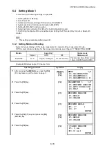
6 SPECIAL MODE (Menu Mode)
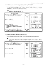
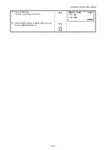
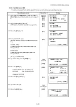
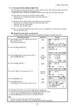
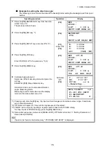
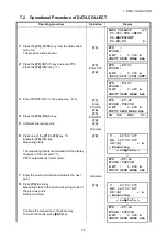
6.6.2 Input Road Data
[ROAD]
is made up of four types of components: LINE, CURVE, SPIRAL and POINT.
To input the required components, carry out the following operating procedure.
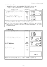
Input LINE data
Operating procedure
Operation
Display
1
After pressing the
{MENU}
key, press the
{F4}
(P
↓
),
{F2}
,
{F4}
key to get the programs menu on page 2/
2.
{MENU}
{F4}
{F2}
{F4}
2
Press the
{F3}
,
{F1}
,
{F2}
,
{F1}
key.
(
Refer to “Input road data” on page 6-26.)
{F3}
{F1}
{F2}
{F1}
The amount of input data varies depending on the type of data, up to a maximum of 30.
(In the case of POINT input only, the maximum is 9 points including end point.)
An error may occur when entering a combination of POINT and other components if the amount of data
entered exceeds the maximum amount allowed for internal calculations. If this happens, please reduce
the amount of input data.
Operating procedure
Operation
Display
1
To input LINE data, press the
{F1}
key. *1)
{F1}
2
Input LENGTH.
3
Press the
{ENT}
key.
4
Input AZIMUTH.
5
Press the
{ENT}
key.
Input
LENGTH
{ENT}
Input
AZIMUTH
{ENT}
*1) The number at the top right of the screen shows the amount of data currently entered.
PROGRAMS 2/2
F1:AREA
F2:POINT TO LINE
F3:ROAD P
↓
F1:LINE
F2:CURVE
F3:SPIRAL
F4:POINT
F1:LINE
F2:CURVE
F3:SPIRAL
F4:POINT
LINE 01
L = 0.000 m
AZ: 0°00’00”
--- --- [CLR] [ENT]
LINE 01
L : 100.000 m
AZ= 0°00’00”
--- --- [CLR] [ENT]
<SET!>


