background image

8

www.topvehicletech.com

If at any point you experience any problems and need any assistance before, during or after the 

installation process, please contact us via : 

Phone:


01420 470 605


E-Mail:


[email protected]

Mon - Fri 9am - 5.30pm GMT

TECHNICAL ASSISTANCE

If you would like to download a digital copy of this manual, or any other product, then please 

visit the 

www.topvehicletech.com

 website.

This manual is considered correct at the time of printing but is subject to change. For the latest 

manuals & updates, refer to our website.

Copyright 2022 by TopVehicleTech.
All rights reserved. No part of this publication may be reproduced, distributed or transmitted 
in any form or by any means, including photocopying, recording, copying or other electronic or 
mechanical methods, without the prior written permission of the author.

Summary of Contents for GRKST02

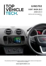
Page 1: ...rovided in this document is subject to change without notice due to changes and or improvements to the product s V1 0722 GRKST02 SEAT IBIZA 6J 2008 2014 INSTALLATION MANUAL This dash image is a visual representation for display purposes only ...

Page 2: ... features a Quadlock connector NB this kit is not viable for facelift models which feature the hazard switch integrated within the head unit If vehicle comes with an OEM bluetooth kit then the fuse for this must be disconnected via the fuseboard See the vehicles manual for locations of where to find this fuse CUSTOMER SUPPORT Installations should be carried out by or under the guidance of an exper...

Page 3: ...g 3 to release the stereo from the cage and repeat the process Fig 1 Fig 2 Fig 3 2 Now that the head unit is exposed undo the 4x screws that hold the head unit in place Once free pull the head unit out of the dashboard and disconnect all of the wiring 3 Take the rear fascia trim and place this onto the dashboard lining this up to the screw holes Once this is lined up correctly use the pre existing...

Page 4: ...stereo and the vehicles pre existing connector 1 Take the steering wheel control interface and attach the 14 way steering wheel harness connector to the relevant side 3 Attach the antenna adapter to the vehicles pre existing connection and the back of new stereo 2 Make a cut within the orange and purple loops on the back of the patch lead connector Then proceed to attach Key 1 to the light blue SW...

Page 5: ...layout may differ dependent on vehicle model STEERING WHEEL CONTROL FUNCTIONALITY MODE 1 2 3 4 5 VOL VOL 1 Volume 2 Volume 3 Track Up 4 Track Down 5 Pick Up Hang Up 1 Volume 2 Volume 3 Track Up 4 Track Down 5 Pick Up Hang Up Original Button New Function ...

Page 6: ...ctor from vehicle Main Wiring Loom Connector 14 Pin Connect to Interface Box Interface Box Flying Wires Pink Speed Pulse Green Park Brake Purple Reverse Gear Blue Amp Remote Stereo Connection Patch Lead Connector 12 Pin Connect to Interface Box Note Must be connected first before power connection is made to the interface ...

Page 7: ...7 www topvehicletech com NOTES ...

Page 8: ...this manual or any other product then please visit the www topvehicletech com website This manual is considered correct at the time of printing but is subject to change For the latest manuals updates refer to our website Copyright 2022 by TopVehicleTech All rights reserved No part of this publication may be reproduced distributed or transmitted in any form or by any means including photocopying re...

Reviews: